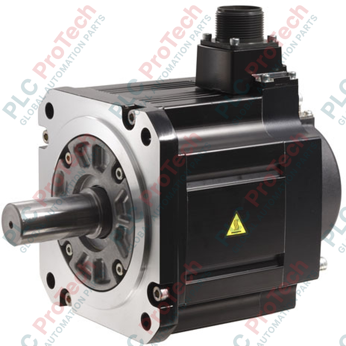
Description
Providing reliable rotational control in demanding industrial environments, the Mitsubishi Electric HG-SR102G7-1/5 is a high-performance medium-inertia AC servo motor equipped with a factory-integrated 1/5 ratio gear reducer. This specialized configuration is engineered to deliver high-torque output at reduced shaft speeds, making it an ideal choice for heavy-duty positioning axes, material handling systems, and automated machinery requiring robust speed-matching capabilities. Operating seamlessly within the MELSERVO-J4 ecosystem, this motor utilizes a high-resolution absolute encoder to guarantee exceptional path accuracy, minimal velocity ripple, and superior thermal efficiency under continuous duty cycles.
Features
-
Medium Inertia Design: Optimizes load-to-motor inertia matching for stable control of heavy or fluctuating mechanical loads.
-
Integrated 1/5 Gear Reducer: Increases output torque while lowering shaft speed, eliminating the need for external, third-party gearboxes.
-
High-Resolution Absolute Encoder: Delivers precise positioning feedback directly to the servo drive without losing home position during power-down cycles.
-
Industrial-Grade Sealing: Built to withstand harsh factory environments, preventing the ingress of dust, non-corrosive liquids, and oil mist.
-
Optimized Heat Dissipation: Compact housing design maximizes surface cooling to maintain reliable operation under high duty cycles.
Applications
-
Packaging & Wrapping Systems: High-torque indexing, continuous feeding, and precision carton sealing mechanisms.
-
Material Handling & Conveyors: Automated sorting, heavy palletizing, and multi-axis transfer tables.
-
Gantry & Cartesian Robots: Overhead axis motion control where load inertia mismatches are common.
-
Metal Processing Machinery: Precision sheet metal bending, feeding, and auxiliary positioning axes.
Technical Specifications Table
| Parameter |
Specification Value |
| Manufacturer |
Mitsubishi Electric |
| Model Code |
HG-SR102G7-1/5 |
| Series |
HG-SR Series |
| Rated Output |
1.0 kW (Motor Base Rating) |
| Rated Speed |
2000 r/min (Motor Base) / 400 r/min (Geared Output) |
| Gear Reduction Ratio |
1/5 (G7 Helical/Offset Gear Option) |
| Inertia Classification |
Medium Inertia |
| Compatible Servo Amplifier |
MR-J4-100A / MR-J4-100B / MR-J4-100GF |
| Power Supply Rating |
3-Phase 200 V AC to 240 V AC |
| Ambient Temperature Limit |
0 to 40 degC (Non-freezing) |
| Country of Origin |
Japan |
| Shipping Weight (Calculated) |
11.0 kg (24.25 lbs) |
Empirical Engineering Insights
Alternative Models & Compatibility
The HG-SR102G7-1/5 is designed to operate directly with the 1.0 kW MR-J4 series servo amplifiers. When replacing legacy HC-SFS102G1 motors, verify the mechanical shaft mounting dimensions, as the HG series incorporates a more compact housing frame. Ensure the servo amplifier parameter configurations are updated via MR Configurator2 to recognize the absolute encoder type associated with the HG-SR series.
Application Pitfalls & Engineering Notes
The G7 integrated gearbox significantly multiplies the motor torque; however, engineers must ensure the peak radial and thrust forces on the output shaft do not exceed the mechanical limits during emergency deceleration. If the mechanical system hits a physical stop, the multiplied torque can shear keyways or damage the gear teeth. Always adjust the torque limit parameters (TL1/TL2) in the MR-J4 amplifier during the commissioning phase to protect the downstream mechanical linkages.
Commissioning & Wiring Tips
Due to the high torque capabilities of this geared motor, any physical vibration can lead to localized electrical noise in the encoder feedback cable. It is critical to use dual-shielded, twisted-pair cables for the encoder run and clamp the shield to the amplifier ground plate. Ensure that power and encoder cables are run in separate, grounded metal conduits or separated by at least 30 cm in open trays to prevent noise induced drive faults (such as AL.30 Regenerative Error or AL.50 Overload).
Installation Guidelines
CRITICAL WARNING
Isolate all primary power sources before mounting or wiring the servo motor. Ensure the internal DC bus capacitors on the companion servo amplifier have fully discharged (verify the charge LED is completely OFF). Failure to disconnect power can result in fatal electrical shock or severe damage to the high-resolution optical encoder assembly.
1
Align the motor and the driven load shaft precisely to prevent coupling stress and premature gear wear. Do not hit the output shaft with a hammer during installation, as this will damage the integrated encoder.
2
Connect the motor power cable to terminals U, V, and W on the servo amplifier. Ensure correct phase rotation, as a mismatch will cause uncontrolled motor runaway.
3
Route the encoder cable separately from the motor power lines and verify that the motor housing is connected to a low-impedance facility protective earth (PE) ground terminal.