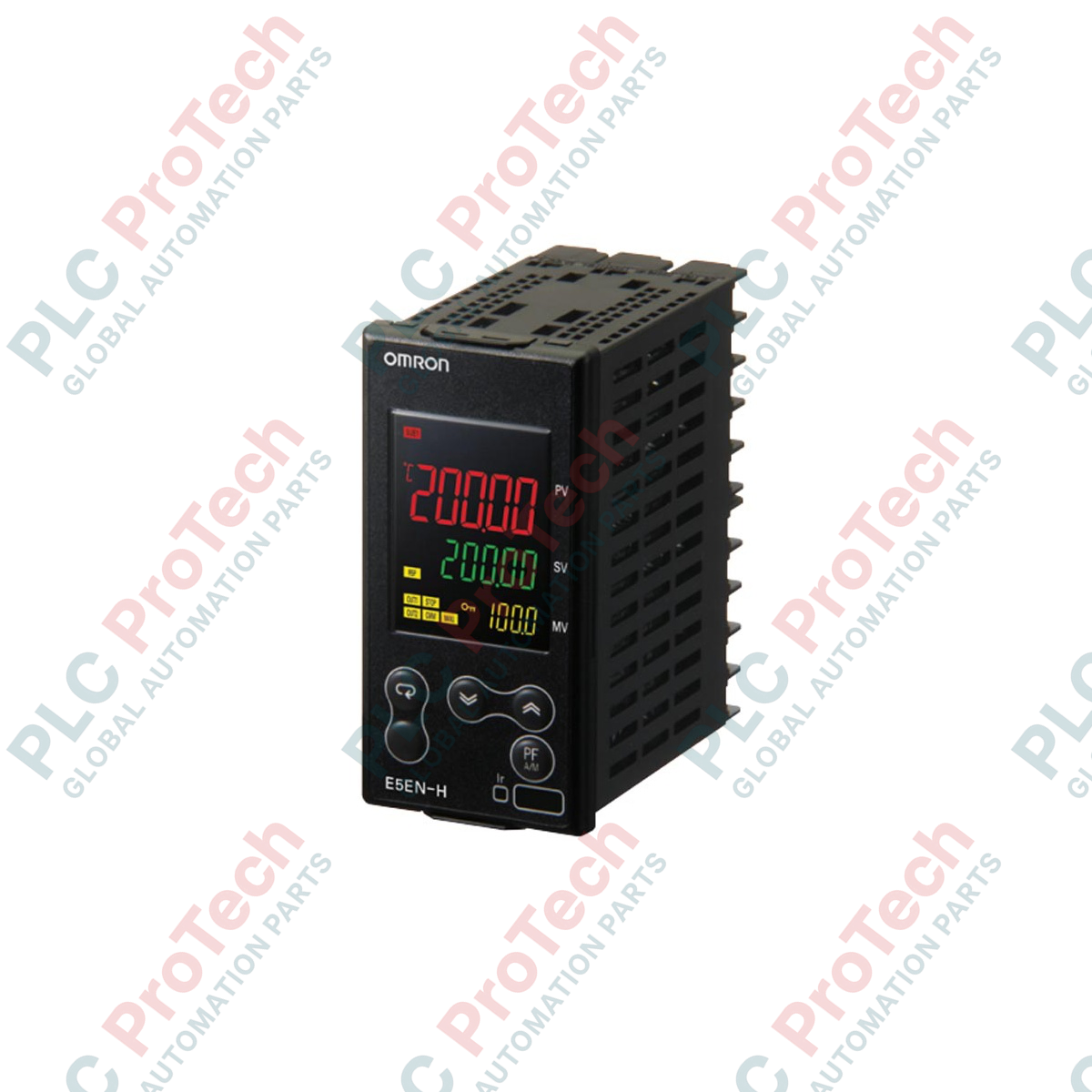
Description
Designed to execute precise closed-loop thermal processes, the Omron E5EN-HPRR2BM-500 is an advanced digital temperature controller featuring position-proportional control and dual relay outputs. This 1/8 DIN panel-mounted instrument integrates auxiliary outputs, event inputs, and an optional unit mounting interface to accommodate complex industrial thermal profiles. Built with non-volatile memory protection rated for up to 1,000,000 write cycles, it ensures configuration security in volatile power environments. The controller comes equipped with a rear terminal cover to meet industrial touch-safe requirements and features a high-grade IP66-rated front panel for resistance to dust and water ingress.
Key Features
-
Position-Proportional Control: Ideal for controlling motorized control valves with high precision.
-
Dual Relay Outputs: Separate open and close control outputs for robust valve manipulation.
-
Two Auxiliary Outputs: Offers additional programmable alarm or signal configurations.
-
Dual Event Inputs: Supports multi-SP selection, run/stop transitions, or auto/manual switching via external dry contacts.
-
IP66 Front Panel: Superior ingress protection suitable for washdown or high-dust industrial environments.
-
Terminal Cover Included: The -500 suffix designates factory-fitted terminal protection preventing accidental contact.
Applications
- Motorized valve modulation in heavy industrial gas and oil combustion furnaces.
- Closed-loop temperature regulation in high-capacity environmental test chambers.
- Extruders and injection molding equipment requiring precise multi-zone thermal management.
- Food processing pasteurizers, retorts, and packaging machinery.
Technical Specifications
| Parameter |
Specification Value |
| Manufacturer |
Omron |
| Model Number |
E5EN-HPRR2BM-500 |
| Control Mode |
Position-proportional control |
| Control Output 1 |
Relay output (Valve open) |
| Control Output 2 |
Relay output (Valve close) |
| Auxiliary Outputs |
2 Independent SPST-NO relay outputs |
| Event Inputs |
2 Inputs (dry contact) |
| Power Supply Voltage |
100 to 240 VAC, 50/60 Hz |
| Operating Voltage Range |
85% to 110% of rated supply voltage |
| Power Consumption |
12 VA maximum (at 100 to 240 VAC) |
| Memory Protection |
Non-volatile memory (1,000,000 write cycles) |
| Ingress Protection Rating |
Front panel: IP66, Rear case: IP20, Terminals: IP00 |
| Dimensions (H x W x D) |
96 mm x 48 mm x 78 mm (1/8 DIN) |
| Shipping Weight (Calculated) |
2.0 kg (including packaging and protective materials) |
Connections and Interfaces
| Terminal Block Section |
Terminal Assignment & Function |
| AC Power Supply |
Terminals 1 & 2 (100 to 240 VAC supply line) |
| Control Output 1 (Open) |
Terminals 3 & 4 (Relay output for motorized valve open action) |
| Control Output 2 (Close) |
Terminals 5 & 6 (Relay output for motorized valve close action) |
| Auxiliary Outputs 1 & 2 |
Dedicated SPST-NO outputs for auxiliary alarm indicators |
| Event Inputs |
Discrete connections for multi-SP switching or run/stop transitions |
Empirical Engineering Insights
Alternative Models & Compatibility
The "H" designation marks the high-performance E5EN variant. Unlike standard E5EN versions, the H-series provides rapid sampling loops (60 ms), improved loop diagnostics, and standard physical modularity options. Ensure your existing controller utilizes position-proportional (P) valve control prior to drop-in swap-outs; replacing standard analog/SSR output E5EN units with this relay-based proportional model requires structural actuator wiring modifications.
Application Pitfalls & Engineering Notes
Under position-proportional control modes, motorized actuator dead-band configuration is critical. Setting an excessively tight dead-band causes relay "chattering" or constant minor adjustments, leading to early mechanical relay fatigue. For heavy industrial service, establish the "Mot Time" (motor calibration time) accurately to reflect the full-travel duration of your control valve from 0% to 100% open.
Commissioning & Wiring Tips
To protect against electrical noise interference with low-level sensor signals, physical separation of high-voltage relay wiring and thermal input circuits must be maintained in the wire duct. Ground all shielded thermocouple or RTD extension wires at a single point inside the main panel, rather than at the controller's terminal block.
Installation Guidelines
CRITICAL SAFETY WARNING: De-energize all primary, auxiliary, and actuator voltage sources before removing or installing the controller. Verify complete residual charge dissipation in any associated capacitive filtering devices to avoid electric shock risks.
1
Prepare a standard 1/8 DIN panel cutout measuring precisely 92 mm (+0.8 mm/-0 mm) wide by 45 mm (+0.6 mm/-0 mm) high.
2
Insert the E5EN-HPRR2BM-500 through the front panel cutout with the water-resistant rubber gasket securely positioned behind the bezel.
3
Slide the mounting adapter brackets onto the controller body from the rear, tightening screws evenly to compress the front-panel gasket to IP66 standards.
4
Complete terminal connections following the designated schematic, apply the -500 rear terminal cover, and verify snug screw terminals to secure contact integrity.