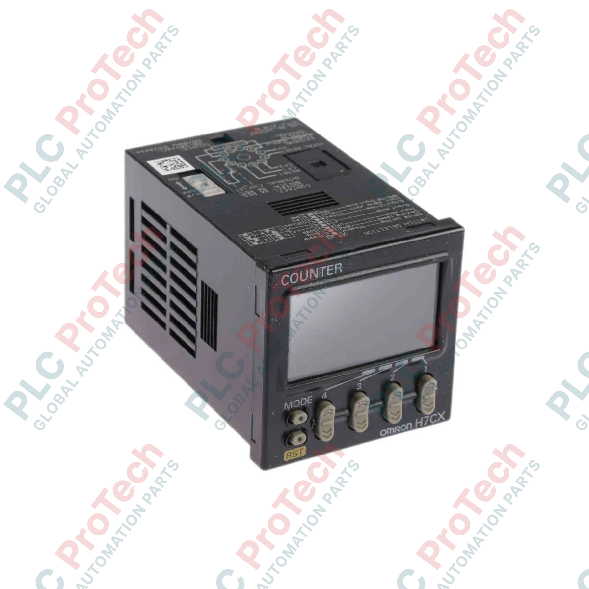
Description
Engineered for high-speed pulse measurement and industrial batch processing, the Omron H7CX-A11-N integrates digital counting and tachometer functionalities into a robust 11-pin socket-mounted configuration. This versatile instrument functions as a multi-stage counter, batch counter, dual counter, or digital tachometer, providing operators with a clear, dynamic dual-color negative transmissive LCD display. Designed for installation into standard 1/16 DIN cutouts, it supports selectable input speeds up to 5 kHz and provides an internal power supply for external sensors, making it an essential control module for manufacturing line integration.
Features
-
Multifunctional Operation: Software-configurable for use as a preset counter, total preset counter, batch counter, dual counter, addition/subtraction counter, or tachometer.
-
Visual Status Indication: High-visibility display dynamically changes backlight color (red/green) based on output states or pre-set target thresholds.
-
Compact Housing: Shorter depth cabinet allows for efficient space utilization behind dense control panels and electrical cabinets.
-
Parameter Protection: Integrated security functions allow engineers to lock specific key operations, preventing unauthorized parameter changes or accidental resets.
-
Sensor Power Output: Provides a stable auxiliary direct-current output to drive local photoelectric or proximity sensors directly from the unit.
Applications
-
Packaging and Bottling: Precise unit-count monitoring for high-speed batching and container filling operations.
-
Rotational Speed Tracking: Conveyor belt rate monitoring and industrial fan rotational speed measurement in tachometer mode.
-
Cut-to-Length Processing: Integration with rotary encoders to control linear cutting machinery in metal or textile plants.
-
Assembling Lines: Step count verification and cycle time tracking on automated sub-assembly cells.
Technical Specifications
| Parameter |
Specification Value |
| Manufacturer |
Omron |
| Model Number |
H7CX-A11-N |
| Supply Voltage |
100 to 240 VAC (50/60 Hz) |
| External Connection |
11-pin circular socket |
| Number of Digits |
6 digits (-99999 to 999999) |
| Max. Counting Speed |
30 Hz or 5 kHz (selectable parameter) |
| Control Output |
SPDT Contact Output (250 VAC, 3 A resistive load) |
| Auxiliary Sensor Power |
12 VDC (+/- 10%), 100 mA |
| Front Panel Protection |
IP66 / NEMA 4X (indoor use when using waterproof packing) |
| Ambient Operating Temperature |
-10 to 55 degC (with no icing or condensation) |
| Dimensions (H x W x D) |
48 mm x 48 mm x 84.1 mm |
| Shipping Weight (Calculated) |
0.25 kg |
| Package Dimensions (Calculated) |
12.0 cm x 8.5 cm x 8.0 cm |
Empirical Engineering Insights
Alternative Models & Compatibility
The H7CX-A11-N directly replaces legacy H7CX-A11 units. When upgrading, note that the "-N" variant features a significantly shallower rear-panel physical depth and a brighter LCD panel. Terminal positions match the standard 11-pin circular socket layout, permitting a drop-in physical exchange without rewiring, though configuration menus must be verified as default parameter ranges may differ slightly from older hardware revisions.
Application Pitfalls & Engineering Notes
When configuring the input logic (NPN vs. PNP), ensure the internal parameter matches the physical wiring. A mismatch will prevent the unit from registering pulses entirely or latch the input in a permanent "on" state. In high-vibration applications, mount the 11-pin socket using retention clips to prevent the counter body from backing out of the socket seat over time.
Commissioning & Wiring Tips
For high-speed inputs (5 kHz setting), always use shielded twisted-pair cabling for signal lines (CP1 and CP2) and route them away from AC power lines or variable frequency drive (VFD) output cables. If you observe random phantom counts, lower the input speed parameter to 30 Hz to activate the internal low-pass digital filter, which effectively suppresses contact bounce noise from mechanical microswitches.
Installation Guidelines
CRITICAL WARNING: Prior to attempting physical installation, panel mounting, or wiring terminal alterations, ensure all AC power feeds to the panel are fully de-energized. Verify the absence of voltage with a calibrated testing instrument to avoid fatal electrical shock or damage to the unit's internal power supply circuits.
1
Insert the counter unit through the standard 45 mm x 45 mm square panel cutout from the front, ensuring the waterproof packing gasket is seated flatly against the panel surface.
2
Slide the mounting adapter bracket onto the rear of the counter from inside the panel, pushing it forward until it firmly locks the device flush against the front faceplate.
3
Align the keying slot of the 11-pin wiring socket with the bottom of the device plug and insert firmly until the pins lock. Complete auxiliary power and sensor input terminations according to your system's schematic diagram.