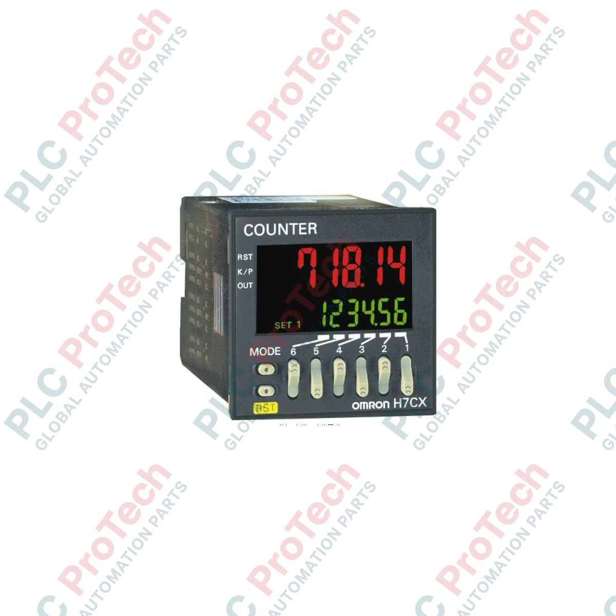
Description
Designed for high-precision rotational speed and flow rate monitoring, the Omron H7CX-R11-N serves as a highly configurable 6-digit digital tachometer within industrial automation loops. This DIN 48 x 48 mm panel-mounted unit provides clear, real-time feedback with its programmable, dual-color negative transmissive LCD display. Engineered for versatility, the system seamlessly interfaces with proximity sensors, rotary encoders, and photoelectric switches, rendering it highly dependable for monitoring complex mechanical speeds. The integrated 11-pin socket configuration facilitates rapid backplane installation and simplified field swaps without disturbing control cabinet wiring layouts.
Features
-
Programmable Color Change: Dynamic red/green display logic allows instantaneous visual warning alerts directly from the factory floor.
-
Broad Input Compatibility: Accepts NPN or PNP transistor inputs and dry contact closures with field-configurable electronic filter speeds.
-
Compact Housing: Space-saving cabinet depth of only 84 mm when paired with standard rear-mounting terminal sockets.
-
Non-Volatile Memory: EEPROM backup guarantees complete configuration and count retention through unexpected power interruption phases.
-
Auxiliary Sensor Power: Built-in 12 VDC power source reduces external component footprints by supplying power directly to primary sensors.
Applications
- Rotational velocity measurements (RPM) on conveyor motor shafts and industrial mixers.
- Flow rate integration and pulse monitoring in water processing plants and chemical dosing skids.
- Line speed tracking and web handling calculations in textile, packaging, and paper conversion processes.
Technical Specifications
| Specification Parameter |
Value / Details |
| Manufacturer |
Omron Industrial Automation |
| Model Number |
H7CX-R11-N |
| Product Type |
Multifunction Counter/Tachometer (Tachometer Mode) |
| Supply Voltage |
100 to 240 VAC at 50/60 Hz |
| Display Digits |
6 digits (range: -99999 to 999999) |
| External Connections |
11-pin socket |
| Output Types |
SPDT Contact (250 VAC / 30 VDC, 3A resistive) and NPN Open Collector (30 VDC, 100 mA max) |
| Max. Input Frequency |
30 Hz or 10 kHz (selectable software parameter) |
| External Power Supply |
12 VDC (plus/minus 10%), 100 mA |
| Operating Temperature |
-10 to 55 degC (no icing or condensation) |
| Mounting Format |
Panel cutout (45 x 45 mm) or surface/DIN-rail with optional socket |
| Shipping Weight (Calculated) |
0.35 kg |
| Package Dimensions (Calculated) |
10.0 cm x 6.0 cm x 6.0 cm |
Connections and Interfaces
| Terminal / Pin Number |
Signal Assignment |
Electrical Specifications |
| Pin 1 |
Signal Input Common (COM) |
0 VDC reference for sensor inputs |
| Pin 2 |
AC Power Supply (L1) |
100 to 240 VAC, 50/60 Hz input |
| Pin 3 |
Sensor Auxiliary Power Source |
12 VDC output, 100 mA maximum |
| Pin 4 |
Input CP1 (Count Pulse 1) |
Tachometer measurement channel A |
| Pin 5 |
Input CP2 / Gate Input (Count Pulse 2) |
Phase measurement channel B or inhibit function |
| Pin 6 |
Reset Input |
Digital reset loop (dry contact or solid-state) |
| Pin 7 |
AC Power Supply (L2/N) |
100 to 240 VAC, 50/60 Hz neutral |
| Pin 8 |
Control Output Contact COM |
Common terminal for mechanical relay |
| Pin 9 |
Control Output Contact NC |
Normally closed relay terminal |
| Pin 10 |
Control Output Contact NO |
Normally open relay terminal |
| Pin 11 |
Transistor Output (Collector) |
NPN Open Collector output, 30 VDC max |
Alternative Models & Compatibility
The updated "N" suffix designation represents Omron's current product revision, replacing legacy H7CX units. It features an optimized casing depth and redesigned menu architectures. Standard 11-pin bases, such as the Omron P2CF-11 (for front-panel mounting) and P3GA-11 (for back-mounting/sub-panel), are fully compatible with this unit, meaning physical infrastructure modifications are unnecessary when upgrading from older H7CX series devices.
Application Pitfalls & Engineering Notes
When deploying the unit as a high-speed tachometer, the input speed selection parameter must be verified. If utilizing mechanical switches or relays as input sensors, the system speed must be set to 30 Hz. Leaving the speed configured to 10 kHz can cause extreme measurement errors due to contact bounce, which the high-speed microprocessor reads as valid pulses. Always isolate control cables from motor power phases to eliminate signal distortion.
Commissioning & Wiring Tips
For electrical noise immunity, ensure that standard NPN/PNP sensor signal lines are run inside grounded metal conduits. If using three-wire proximity sensors, configure the internal logic parameter via the system menus to match your sensor configuration. Pin 3 supplies 12 VDC; please confirm that the total current draw of connected sensors does not exceed 100 mA, or else the internal overload protection will trigger, resulting in device measurement failure.
Installation Guidelines
CRITICAL WARNING
Isolate and de-energize all AC power sources feeding the control enclosure prior to handling terminals or plugging the 11-pin unit into its socket. Failure to safely isolate these circuits can result in severe electrical shock, component failure, or permanent destruction of the internal solid-state components.
1
Ensure a standardized panel cutout of 45 x 45 mm (1/16 DIN) is prepared on a clean panel surface free of metallic dust.
2
Wire the 11-pin terminal socket (e.g., P2CF-11) firmly in accordance with the terminal pin diagram, securing screw terminals with a maximum torque of 0.5 N-m.
3
Insert the main housing into the panel cut-out from the front, then secure it using the Y92F-30 adapter from the rear.
4
Apply power, step through the basic programming modes to establish input speed parameters, output response times, and target scaling limits before turning on field machinery.