Description
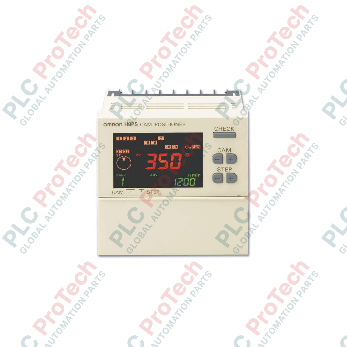
Executing high-speed, angle-based control with microsecond precision, the Omron H8PS-16BFP acts as a robust solid-state replacement for traditional mechanical cam switches in high-performance automation environments. This 1/4 DIN Cam Positioner features 16 integrated PNP transistor outputs, enabling direct control interfacing with PLC input cards, safety systems, and industrial solenoid valves. Designed with a clear, backlit LCD interface, the controller provides real-time angular updates, rotational speeds (r/min), and active output step cycles to maintenance staff and machine operators directly on the panel face.
Key Technical Features
-
16 PNP Transistor Outputs: High-density discrete output array tailored for modern source-type control architectures.
-
On-Unit DIP Switch: Allows quick hardware configuration to swap the encoder's operational rotation direction between forward (CW) and reverse (CCW).
-
Backlit LCD Panel: Delivers sharp visualization of process variables, current rotational angles, and visual diagnostics under low-light floor conditions.
-
Flexible Mount Options: Native housing structure supports both space-saving DIN-rail tracking and secure flush on-panel mounting.
-
Microsecond Processing Response: Mitigates synchronization lag at high shaft velocities, protecting mechanical equipment from cycle drift.
Industrial Applications
-
Rotary Indexing and Tooling Tables: Precision alignment of multi-station machining tools with absolute table position.
-
High-Speed Packaging Machinery: Regulates the timing of rotary sealing jaws, packaging feed systems, and adhesive gun triggers.
-
Mechanical Presses and Metal Stamping: Synchronizes feed cycles, workpiece clamp actions, and die-protection systems with the crankshaft angle.
-
Automated Assembly Lines: Coordinates multi-axis pick-and-place systems operating along cyclic trajectories.
Technical Specifications
| Manufacturer |
Omron |
| Model / SKU |
H8PS-16BFP |
| Device Classification |
Cam Positioner |
| Output Points |
16 Outputs |
| Output Logic Type |
PNP Transistor |
| Input Type |
Absolute Encoder Input |
| Supply Voltage Range |
24 VDC (Acceptable operating ripple range: 20.4 to 26.4 VDC) |
| Form Factor Size |
1/4 DIN (96 x 96 mm faceplate) |
| Display Technology |
LCD with standard integrated backlight |
| Operating Temperature Range |
-10 to +55 degC (with no icing or condensation) |
| Net Unit Weight |
Approx. 300 g |
| Shipping Weight (Calculated) |
1.5 kg (with protective packaging) |
| Unit Dimensions (W x H x D) |
96 mm x 121.2 mm x 58 mm |
Connections and Interfaces
| Terminal / Port Designation |
Functional Assignment |
| Power Supply Terminals (+ / -) |
24 VDC System Power Input and Ground |
| Dedicated Circular Port |
Absolute Encoder Input Connection |
| Discrete Inputs (RUN, RESET, BANK) |
Mode switches, external reset trigger, and program selection |
| OUT 1 through OUT 16 |
PNP Sourcing Transistor Signal Outputs |
| Vcc / COM (Output Common) |
External load power reference connection |
Alternative Models & Compatibility
The H8PS-16BFP utilizes active-high PNP transistor outputs. It cannot serve as a direct drop-in replacement for the NPN-logic equivalent model (H8PS-16BF) without modifying the external receiver card's reference wiring. Ensure that any paired absolute rotary encoders (such as the Omron E6C3-AG5B series) also utilize matching PNP complementary or open-collector output topologies to prevent damage to the encoder input circuitry.
Application Pitfalls & Engineering Notes
When running rotational systems at high speeds (exceeding 1000 RPM), ensure that the resolution settings of the H8PS-16BFP match the physical capabilities of your encoder. Selecting high-density resolution parameters under extreme shaft speeds can trigger internal processor buffer errors if the input frequency limit is exceeded. Always utilize twisted, shielded signal pairs to connect absolute encoders, and route them far from high-current variable frequency drive (VFD) output runs to eliminate high-frequency electromagnetic interference.
Installation Guidelines
CRITICAL WARNING: HIGH VOLTAGE AND MOVEMENT RISK
Before beginning mechanical installation or wire termination, fully disconnect all electrical power sources driving the host machine and the positioner unit. Confirm the prime mover's rotary shaft is physically locked in place to prevent accidental rotation and mechanical crush hazards during encoder pairing.
1
Cut the required 92 mm x 92 mm square panel opening if utilizing front flush-panel mounting, or snap the integrated mounting adapter directly onto standard 35 mm DIN-rail.
2
Securely seat the absolute rotary encoder cable into the designated positioner port, aligning the pin-key correctly before turning the threaded collar.
3
Wire the 24 VDC power lines to the terminal block, ensuring correct polarity. Connect the 16 PNP outputs to their corresponding control destinations.
4
Apply power, check the LCD interface diagnostics, and configure the encoder's direction DIP switches based on actual mechanical rotation pathways.