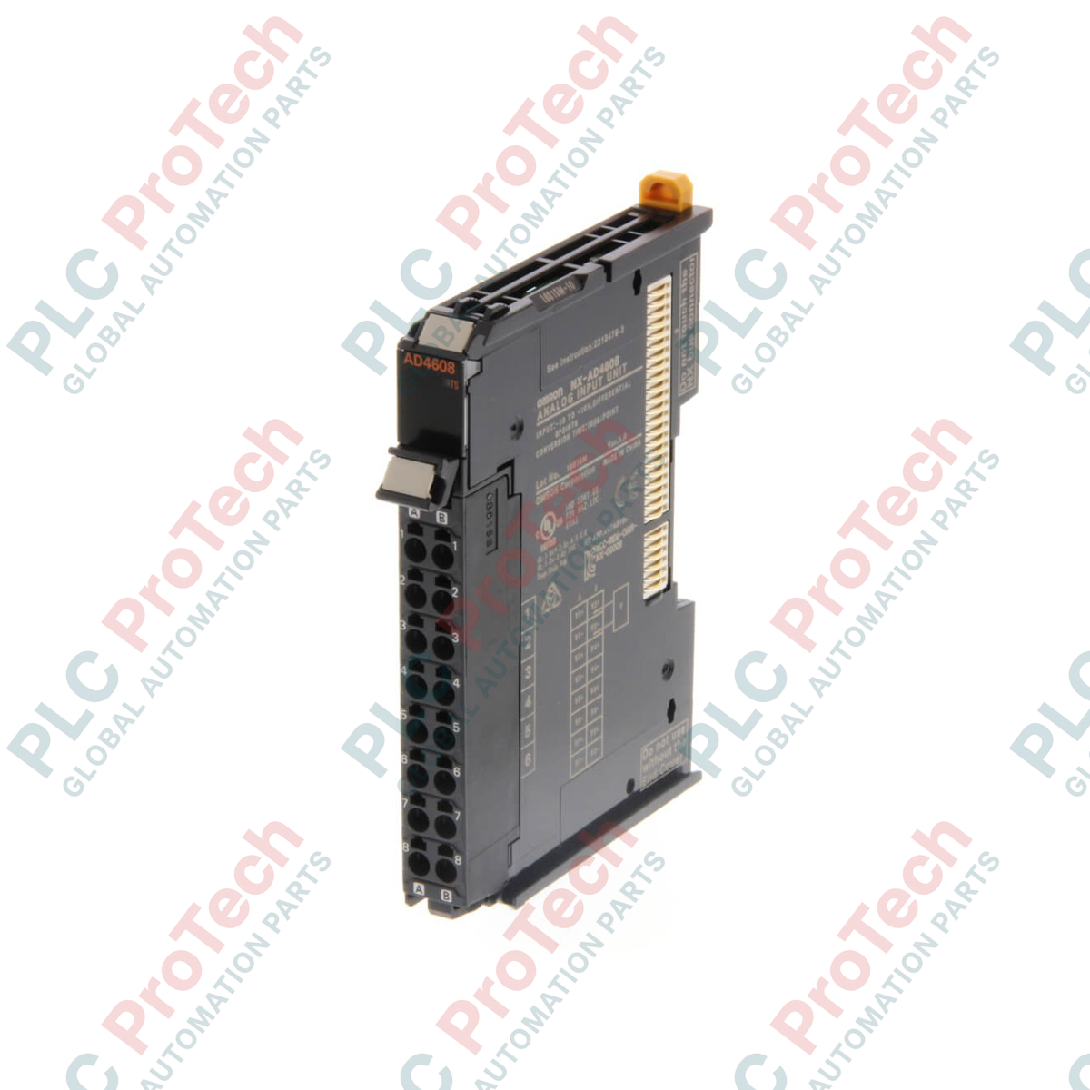
Description
Optimized for precision industrial monitoring and high-speed motion synchronization, the Omron NX-AD4608 processes up to eight independent differential analog voltage signals. As an integral component of the Omron NX I/O bus system, this module interfaces directly with Sysmac NJ/NX controllers and EtherCAT or EtherNet/IP bus couplers to feed reliable sensor data back to the central processor. Its 15-bit high-resolution digital converter translates -10 to 10 V industrial inputs with exceptional fidelity, while a 0.08 ms conversion speed per unit ensures performance levels match rigorous real-time loop execution demands.
Features
-
High-Speed Synchronous Conversion: Extremely fast conversion time of 0.08 ms per unit for latency-critical control applications.
-
Eight Differential Inputs: Differential configuration helps suppress common-mode electromagnetic noise on low-voltage analog paths.
-
Sysmac System Integration: Supports synchronous I/O refreshing when used with NX-series EtherCAT Coupler and NJ/NX controllers.
-
Push-in Plus Terminal Blocks: Simplifies field installation with tool-free, high-retention front-facing connections.
-
Detachable Connector: Enables rapid module replacement without needing to disconnect individual field wires.
Applications
- High-speed multi-axis motion and position feedback systems.
- Precision pressure, flow, and temperature transmitter interfacing.
- Dynamic voltage surveillance inside industrial control cabinets.
- OEM machine building in packaging, assembly, and materials handling industries.
Technical Specifications
| Parameter |
Specification Value |
| Manufacturer |
Omron |
| Model / SKU |
NX-AD4608 |
| Series |
NX Series I/O System |
| Input Type |
Linear Analog Voltage (-10 V to 10 V) |
| Number of Analog Inputs |
8 |
| Input Circuit Type |
Differential |
| Resolution |
15-Bit |
| Conversion Time |
0.08 ms/unit |
| Signal Refreshing Method |
Synchronous / Free-run refreshing |
| I/O Connection Type |
Push-in Plus (16 terminals, detachable) |
| Ingress Protection Rating |
IP20 |
| Dimensions (W x D x H) |
12 mm x 71 mm x 100 mm |
| Weight (Calculated) |
0.07 kg |
Empirical Engineering Insights
Alternative Models & Compatibility
The NX-AD4608 is primarily applied where voltage signal integrity is critical. If your application calls for analog current processing (e.g., 4-20 mA), the NX-AD4208 is the sister unit designed to meet those specific engineering criteria. Ensure your Sysmac Studio software package is updated to at least v1.10 to guarantee seamless configuration, mapping, and calibration diagnostics for the 8-channel input array.
Application Pitfalls & Engineering Notes
Differential signaling is superb at cancelling noise, but only if sensor power supply grounds are properly referenced. When wiring non-isolated transmitters, tie the transmitter negative power rail back to the common ground of the I/O bus power supply. Failure to address this ground loop differential can result in sensor signal clipping, high-voltage offset errors, or unexpected scaling saturation at the CPU level.
Commissioning & Wiring Tips
Use shielded twisted-pair (STP) cabling for all eight differential runs. Ground the shield at only one physical point (typically the clean instrumentation ground rail in the main cabinet) to avoid induced current loops. Because of the compact 12 mm module profile, space inside the terminal area is restricted. Employing ferrules with a plastic collar on your Push-in Plus connections guarantees clean insertion and eliminates stray wire strands that can bridge adjacent channels.
Installation Guidelines
CRITICAL WARNING: Completely de-energize the entire control panel, including the NX-series main bus coupler power supply and all auxiliary sensor field power lines, before mounting or removing the input unit. Operating under tension can result in backplane communication damage, controller faults, or severe electrical shock to personnel.
1
Align the top and bottom guide rails of the NX-AD4608 with the adjacent NX unit on the DIN rail.
2
Slide the module firmly toward the left-side unit until you hear the mechanical locking tab click. Secure the yellow DIN hook on the bottom.
3
Insert clean, ferruled signal lines into the Push-in Plus terminal block. Push the terminal straight back to secure, then gently tug each wire to verify mechanical retention.
4
Apply system power and verify that the local "TS" LED indicator displays solid green, confirming established system communication and status checks.