Description
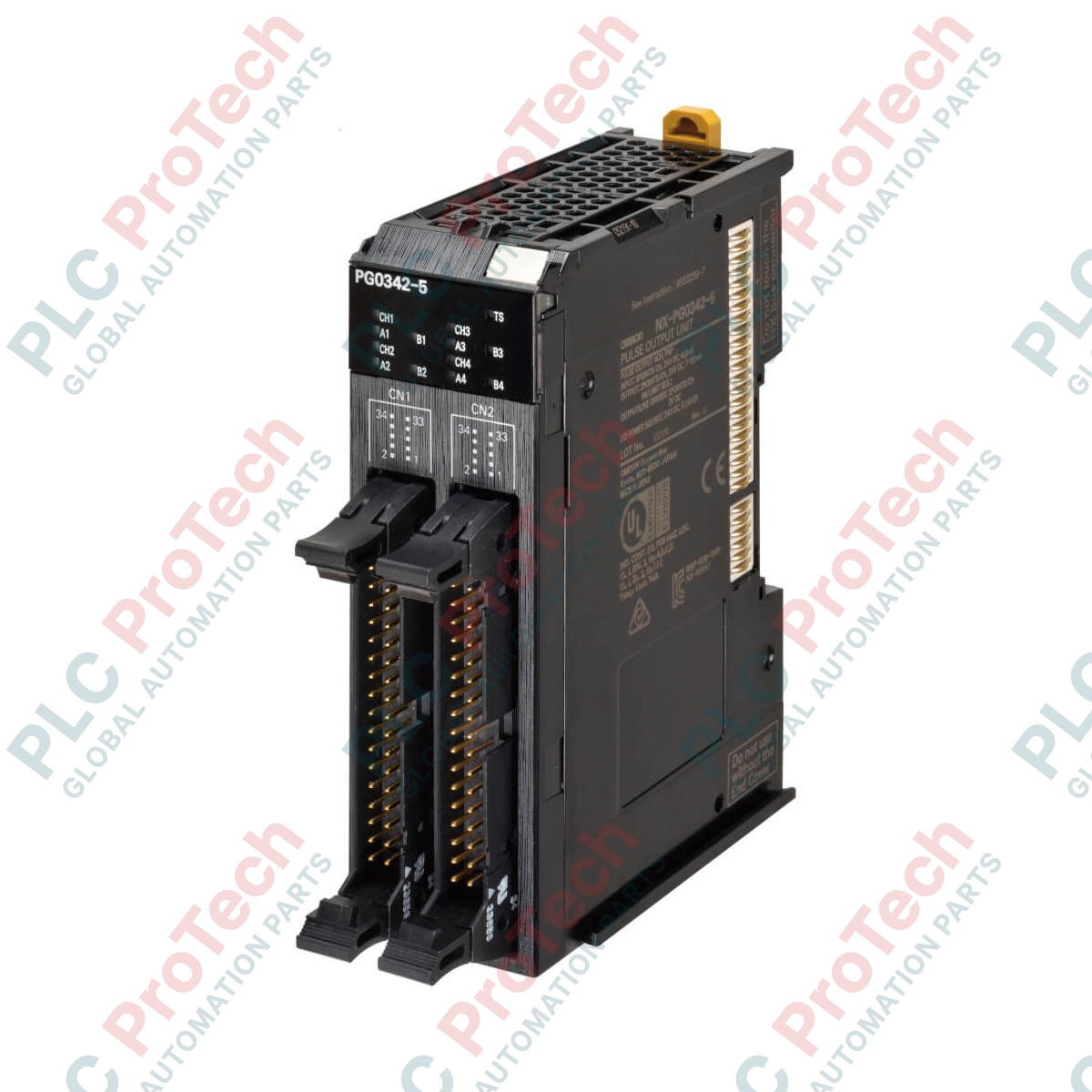
Designed for high-performance motion coordination within Sysmac automation architectures, the Omron NX-PG0332-5 Pulse Output Unit delivers precision multi-axis open-loop control for servo and stepper systems. This specialized slice I/O module integrates seamlessly into the NX Series platform, offering 4 high-speed channels with line driver outputs designed for high-noise immunity and long-distance transmission. Utilizing synchronous I/O refreshing, the unit synchronizes pulse outputs with the primary EtherCAT controller cycle, eliminating jitter and guaranteeing deterministic positioning for demanding packaging, assembly, and indexing applications.
Key Features
-
4 Independent Channels: Multi-axis positioning capabilities within a compact 30mm width factor.
-
High-Speed Line Driver Output: Achieves a maximum pulse rate of 4,000,000 pps for high-resolution positioning.
-
Synchronous Refreshing: Aligns I/O execution directly with the primary task period of the Sysmac NJ/NX controller.
-
Dual MIL Connectors: High-density 34-pin external connections simplify cabinet pre-wiring and reduce physical footprint.
-
Flexible Pulse Modes: Supports forward/reverse direction, pulse plus direction, and 1x/2x/4x phase differential modes.
Applications
- High-speed labeling and packaging machinery.
- Multi-axis cartesian gantries and pick-and-place robots.
- Semiconductor wafer handling and alignment tables.
- Feeding systems for metal stamping and forming presses.
Technical Specifications
| Parameter |
Specification |
| Manufacturer |
Omron |
| Model Number |
NX-PG0332-5 |
| Module Type |
Pulse Output Unit (NPN Type) |
| Number of Channels |
4 Channels |
| Pulse Output Form |
Line driver output |
| Max Pulse Output Speed |
4,000,000 pps (4 Mpps) |
| I/O Refreshing Method |
Synchronous I/O refreshing or task period prioritized refreshing |
| Positioning Range |
-2,147,483,648 to 2,147,483,647 pulses |
| Velocity Control Range |
1 to 4,000,000 pps |
| Inputs per Channel |
5 external inputs |
| Outputs per Channel |
5 outputs (1 forward, 1 reverse pulse, 3 external outputs) |
| Current Consumption |
50 mA max per connector from I/O power supply |
| External Connection |
MIL connector (34 terminals x 2) |
| Dimensions (W x H x D) |
30 x 100 x 71 mm |
| Weight |
0.15 kg |
Connections and Interfaces
| Terminal Type |
Signal Assignment |
Cable Limits |
| MIL Connector (Pins 1-34, A/B) |
Line driver outputs, home/limit inputs, and auxiliary I/O |
10 m max (Line Driver), 3 m max (Other I/O) |
Empirical Engineering Insights
Alternative Models & Compatibility
The NX-PG0332-5 is designed to interface with third-party drives via standard MIL connectors. For point-to-point wiring to non-MIL drive terminal blocks, engineers should utilize the Omron XW2R series connector-terminal conversion units alongside pre-assembled XW2Z cables to prevent signal cross-talk and connection errors.
Application Pitfalls & Engineering Notes
Because this module utilizes line driver outputs, it cannot be directly wired to single-ended (open-collector) stepper or servo inputs without an external differential-to-single-ended signal converter. Attempting to drive single-ended circuits directly will cause signal distortion, loss of position synchronization, or damage to the output driver stage.
Commissioning & Wiring Tips
To guarantee signal integrity up to the maximum 4,000,000 pps frequency, use shielded twisted-pair (STP) cabling for the MIL interface. Connect the cable shield directly to the functional ground bar of the control panel, keeping the unshielded wire ends inside the drive enclosure as short as possible to minimize high-frequency noise susceptibility.
Installation Guidelines
CRITICAL WARNING: Prior to mounting, wiring, or maintenance, isolate all primary and auxiliary power supplies feeding the NX Bus and the physical servo/stepper drives. Failure to do so may result in electric shock, unauthorized motion commands, or permanent hardware failure.
1
Align the alignment groove of the NX-PG0332-5 with the slide guide of the adjacent NX module or the NX-bus connector on the coupler.
2
Press the unit straight onto the DIN rail until you hear an audible click from the locking hooks locking it securely into place.
3
Attach the dual MIL cables, ensuring both lateral locking clips on the connectors click into place to maintain reliable electrical contact.