Description
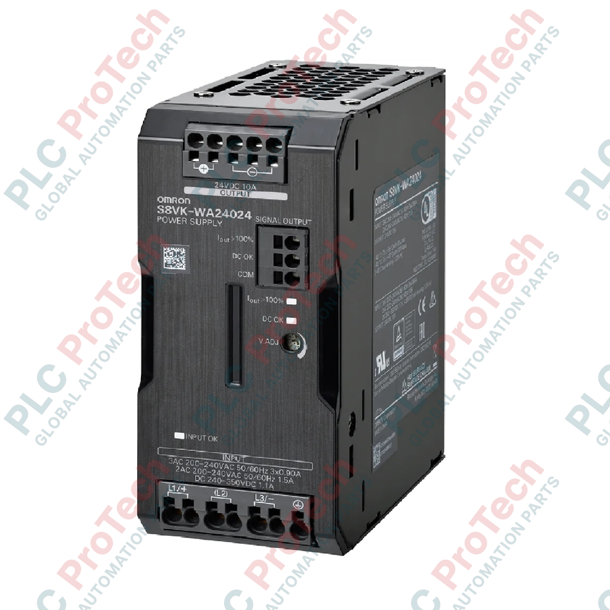
Operating as a high-efficiency electrical conversion module, the Omron S8VK-WA24024 delivers stable direct current to demanding industrial automation networks from a three-phase power source. This switch-mode power supply is engineered to mitigate phase unbalance risks and provide continuous, reliable 24 VDC output within compact control cabinets. Designed with a robust covered housing and integrating Omron's proprietary Push-In Plus terminal connection technology, the unit minimizes installation labor while maximizing resistance to physical vibrations common in heavy industrial manufacturing environments.
Features
-
Three-Phase Input: Supports input ranges from 200 to 240 VAC, reducing neutral current loading and balancing phases.
-
Push-In Plus Terminals: Enables rapid, tool-free wiring that maintains continuous tension to prevent terminal loosening under vibration.
-
Dynamic Current Boost: Delivers up to 15 A of maximum boost current to support high-inrush startup loads such as solenoids, motors, and capacitive circuits.
-
Space-Saving Footprint: Highly compact side-by-side mounting design optimizes DIN-rail space allocation.
-
IP20 Protection: Covered construction provides finger-safe operation and compliance with EN/IEC 60529 standards.
Applications
- Automotive assembly machinery control panels
- High-speed packaging and sorting systems
- Semiconductor fabrication tool power distribution
- Water and wastewater treatment processing equipment
- General manufacturing plant PLC and sensor power networks
Technical Specifications
| Specification Parameter |
Verified Engineering Value |
| Manufacturer |
Omron |
| Model Number |
S8VK-WA24024 |
| Series Name |
S8VK-W |
| Rated Input Voltage |
200 to 240 VAC (Three-Phase) |
| Power Rating |
240 W |
| Rated Output Voltage |
24 VDC |
| Rated Output Current |
10 A |
| Maximum Boost Current |
15 A |
| Terminal Type |
Push-In Plus Terminal Block |
| Construction Type |
Covered |
| Degree of Protection |
IP20 (EN/IEC 60529) |
| Unit Weight |
0.8 kg |
| Shipping Weight (Calculated) |
2.0 kg |
Connections and Interfaces
| Terminal Block Section |
Terminal Designation |
Functional Assignment |
| Input Terminals (Top) |
L1 |
AC Input Phase 1 |
| L2 |
AC Input Phase 2 |
| L3 |
AC Input Phase 3 |
| PE (Ground Symbol) |
Protective Earth Ground (Safety Ground) |
| Output Terminals (Bottom) |
+V (1) |
Positive 24 VDC Output Line 1 |
| +V (2) |
Positive 24 VDC Output Line 2 |
| -V (1) |
Negative 24 VDC Output Line 1 (Return) |
| -V (2) |
Negative 24 VDC Output Line 2 (Return) |
Empirical Engineering Insights
Alternative Models & Compatibility
The S8VK-WA24024 serves as a more reliable alternative to single-phase S8VK-G or S8VK-X units when deployed in facilities suffering from persistent neutral line noise or phase unbalance. Because it derives power across three balanced phases, it prevents the local neutral circuit from overheating. When substituting this unit for older legacy switch-mode models, verify the 3-phase line configuration, as this module requires a nominal input of 200 to 240 VAC to meet the rated 240W threshold.
Application Pitfalls & Engineering Notes
A common mistake during panel integration is overloading the 15 A boost current duration. While the S8VK-WA24024 cleanly handles up to 150% of its rated capacity, this boost is strictly rated for temporary duty cycles. Continuous operation beyond the designated peak window will trigger thermal overcurrent protection, causing the output voltage to dip or cycle. Ensure the control cabinet maintains at least 15 mm of free spacing on both side panels and 50 mm vertically to allow optimal convection cooling, as restricted air passage accelerates thermal degradation.
Commissioning & Wiring Tips
To ensure gas-tight connections with the Push-In Plus mechanism, strip solid conductor wires or crimped ferrules to exactly 10 mm. When introducing stranded wires without ferrules, utilize a flathead precision screwdriver to depress the orange release tab prior to inserting the wire. Avoid twisting the stranded wires to prevent individual copper strands from splaying, which can lower the effective contact cross-section and generate localized hotspot resistance.
Installation Guidelines
CRITICAL WARNING: De-energize all primary and secondary electrical systems before attempting installation, wiring, or physical inspection of the S8VK-WA24024. Confirm that the input line voltage matches the rated three-phase range (200 to 240 VAC) to prevent immediate terminal and internal capacitor damage.
1
Mount the power supply unit securely onto a standard 35mm DIN rail. Ensure the lock lever on the back of the chassis snaps firmly into place.
2
Wire the Protective Earth (PE) terminal first to a certified panel ground bus to establish appropriate EMI suppression and fault safety pathing.
3
Insert the three incoming phase wires (L1, L2, L3) into the top terminal block blocks, verifying that each wire is locked securely into position.
4
Connect the 24 VDC system load lines to the corresponding +V and -V output terminals located on the bottom block. Double-check polarity alignment before applying line voltage.