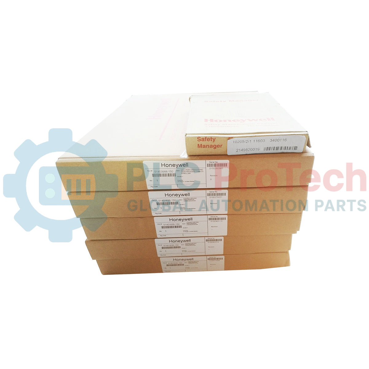
Honeywell 10205/2/1 (ordering code 11600) is a two-channel fail-safe analog output module for the Honeywell Fail Safe Control (FSC) platform. Each channel delivers a configurable 0–20 mA or 4–20 mA current signal in an active (internally powered) or passive (externally powered) loop arrangement. It is intended for non-redundant FSC I/O configurations; the output currents cannot be paralleled for redundant operation.
Technical Specifications
| Manufacturer |
Honeywell Safety Management Systems |
| Product / order code |
10205/2/1 / 11600 |
| Platform |
Honeywell FSC (Fail Safe Control) |
| Module function |
Fail-safe analog current output |
| Number of outputs |
2 |
| Output ranges |
0–20 mA or 4–20 mA; active or passive loop modes |
| D/A conversion |
12-bit per output; A/D output-value monitoring for diagnostics |
| 5 VDC supply requirement |
30 mA |
| 24 VDC supply requirement |
65 mA base load, plus 30 mA for each active output |
| Off-state current |
Less than 0.05 mA |
| Active output: maximum loop resistance |
1 kΩ |
| Active output: maximum output voltage |
30 VDC |
| Passive output: external supply |
40 VDC maximum; minimum module voltage drop 7.5 V |
| Watchdog input current |
0.5 mA |
| Isolation |
Analog outputs isolated from 5 VDC and 24 VDC supplies; output 0 V terminals internally commoned |
| Rack space |
4 HP (4 TE), 3U (3 HE) |
| Module / rack key coding |
A9 and C5 |
| Historical software requirement |
FSC software version 3.00 as listed in the Hardware Manual; verify installed system release |
| I/O redundancy |
Non-redundant I/O configurations only |
Output Modes and Termination
When used with FSC I/O backplanes, each output requires a corresponding 10205/A/. analog output mode module at the backplane programming connector. The 10205/A/1 configures internally powered current-source operation for a passive field load; 10205/A/2 configures externally powered current regulation for an active field device. The 10205/A/3 dummy mode module is used to terminate an unused output channel. Verify which mode card is installed on each channel before replacing the output module.
The historical FSC manual permits resistive or capacitive loads; inductive loads may trigger module fault reporting. The 24 VDC feed remains necessary even when a loop is configured for external power. On an unused channel, the required dummy or specified shorting arrangement prevents the module's self-test from raising a fault.
Diagnostics and Commissioning
Each channel includes D/A conversion and an A/D readback path. The FSC system can check output-value agreement, ability to de-energize, and cross-channel effects within the configured process safety time. This diagnostic architecture does not establish that a particular installed application meets a safety integrity level by itself; the configured system and field circuit must be evaluated independently.
During replacement, document the original 10205/2/1 11600 order code, rack keying, backplane type, installed 10205/A mode cards, loop wiring, control-system release and process safety configuration. After controlled installation, verify the output ranges, loop current with an appropriate meter, unused-channel termination, watchdog response and fault indication under site-approved commissioning procedures. The module has P2/P3 calibration potentiometers; do not alter calibration without the FSC procedure and suitable test equipment.
Dimensions, Weight and Air-Freight Planning
The Honeywell hardware manual specifies 4 HP × 3U rack space, not a complete shipping-carton dimension. Historical spare-parts listings report an approximate module envelope of 175 × 125 × 25 mm, but these measurements and the listed net weights differ between suppliers; confirm the actual stocked unit before treating them as final dimensions or weight.
Estimated protective package: 240 × 180 × 90 mm. Estimated shipping weight: 0.8 kg. These are preliminary courier/freight-planning estimates, not Honeywell OEM package specifications. Final chargeable dimensions and gross weight must come from the warehouse after protective packing. The previous draft's 325 × 150 × 150 mm figure appears in third-party documentation for a separate associated termination/motherboard assembly and must not be presented as the physical dimensions of the 10205/2/1 module.
Ordering and Replacement Information
Module: 10205/2/1. Ordering code: 11600. Confirm the complete marking on the stocked unit and whether the required 10205/A/1, /A/2 or /A/3 mode cards, termination assembly and cables are supplied separately. Do not assume 10205/1/1 is an unconditional plug-in replacement: its rack keying and system implementation differ. Availability and exact package measurements should be reconfirmed before shipment.