


Replacing a Beckhoff EL4032: Wiring and Output Checks
A field checklist for replacing a Beckhoff EL4032, covering the ±10 V load, terminal map, power contacts, EtherCAT state, and watchdog behavior.
Manufacturer: ABB
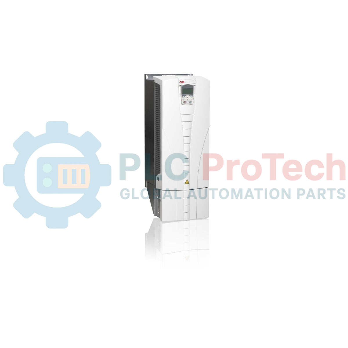
Product No.: ACS550-01-125A-4
Country of origin:Sweden
Product Type: Azionamenti a frequenza variabile
Barcode: 85044095
Payment: T/T, Western Union
Weight: 34000g
Dimensions: 265 mm (W) x 739 mm (A) x 286 mm (P)
Shipping port: Xiamen
Warranty: 12 months
Operando su reti elettriche industriali trifase, il variatore di frequenza ABB ACS550-01-125A-4 fornisce la regolazione della velocità e della coppia per motori asincroni trifase. Progettato per applicazioni a servizio normale fino a 55 kW (100 HP), questo variatore combina il controllo vettoriale, il controllo scalare e un'induttanza a reattanza oscillante integrata per la riduzione delle armoniche, ottimizzando le prestazioni meccaniche e l'efficienza energetica. L'unità è alloggiata in un robusto involucro IP21 (UL Tipo 1), che la rende adatta al montaggio affiancato in armadi standard o all'integrazione diretta a parete in ambienti industriali puliti e asciutti.
| Parametro | Valore / Specifica |
|---|---|
| Produttore | ABB |
| Numero modello | ACS550-01-125A-4 |
| Intervallo di tensione in ingresso | 380 - 480 V CA (trifase) |
| Intervallo di frequenza in ingresso | 48 a 63 Hz |
| Potenza di uscita (uso normale) | 55 kW / 100 HP |
| Corrente di uscita (uso normale) | 125 A |
| Grado di protezione dell'involucro | IP21 (UL Tipo 1) |
| Dimensioni del telaio | R4 |
| Intervallo di temperatura operativa | -15 a 40 °C (senza declassamento) / fino a 50 °C (con declassamento) |
| Peso di spedizione (calcolato) | 34.00 kg |
| Dimensioni dell'imballaggio (calcolate) | 265 mm (W) x 739 mm (H) x 286 mm (D) |
| Codice merceologico | 85044095 |
| Morsetto / Porta | Assegnazione di funzione / segnale |
|---|---|
| U1, V1, W1 | Morsetti di alimentazione in ingresso dalla rete CA trifase |
| U2, V2, W2 | Morsetti di uscita per il collegamento di motori trifase |
| UC+, UC- | Collegamento del bus CC (per moduli chopper di frenatura dinamica) |
| X1: AI1 / AI2 | Ingressi analogici programmabili (Tensione 0-10V, Corrente 0/4-20mA) |
| X1: da DI1 a DI6 | Ingressi digitali programmabili (PNP/NPN, alimentazione ausiliaria 24V DC) |
| X1: RO1, RO2, RO3 | Uscite relè programmabili a contatto di scambio (250V AC / 30V DC, max 2A) |
L'ACS550-01-125A-4 fa parte della collaudata linea ACS550. Per i percorsi di migrazione moderni o la pianificazione di nuove infrastrutture, l'ABB ACS580-01-124A-4 è il sostituto hardware diretto. Si noti che, durante la migrazione alla serie ACS580, i modelli del pannello di controllo e i set di parametri seriali devono essere aggiornati, poiché gli indici dei parametri e i profili software differiscono tra il firmware ACS550 precedente e le piattaforme Drive-to-Drive più recenti.
Per prevenire l'accumulo termico, assicurarsi di lasciare uno spazio libero minimo di 200 mm sopra e sotto il frame R4 quando viene montato all'interno di quadri elettrici. L'azionamento di carichi ad alta inerzia, come pesanti ventilatori di ventilazione o centrifughe industriali, senza una resistenza di frenatura può causare interventi per sovratensione (Fault 2 - DC OVERVOLT) durante rampe di decelerazione rapide. Per mitigare questo problema, configurare il parametro del drive per utilizzare la funzione "deceleration-limit" oppure integrare un'unità chopper di frenatura dinamica esterna.
Configurare sempre la Macro applicativa corretta (ad esempio HVAC, controllo a 3 fili o PID) durante l'avvio iniziale, poiché la modifica successiva della macro ripristinerà i valori predefiniti e sovrascriverà l'instradamento personalizzato degli ingressi digitali. Per ridurre il rumore elettrico ad alta frequenza, utilizzare cavi motore schermati e simmetrici e mettere a terra la schermatura a 360 gradi sia sulla piastra del morsetto PE del VFD sia sulla scatola morsetti del motore.
AVVERTENZA CRITICA: PERICOLO ELETTRICO
Prima di iniziare l'installazione o la manutenzione, isolare tutte le linee di alimentazione in ingresso. Attendere almeno 5 minuti dopo aver scollegato l'alimentazione per consentire la completa scarica dei condensatori del bus CC interno. Verificare sempre l'assenza di tensione sui morsetti U1/V1/W1, U2/V2/W2 e UC+/UC- con un multimetro certificato prima di maneggiare i morsetti di collegamento.

Global Express Shipping
Returns & Warranty


Global Express Shipping
Returns & Warranty
Orders are processed and delivered Monday-Friday (excluding public holidays).
For full eligibility, restocking fees, and international return details, please view our official Refund & Return Policy .
| Country of origin |
Sweden
|

A field checklist for replacing a Beckhoff EL4032, covering the ±10 V load, terminal map, power contacts, EtherCAT state, and watchdog behavior.

Before replacing a Yokogawa AAI835, verify the 4-in/4-out channel map, power-loss loop behavior, barrier type, output load, cable, and redundancy.

ABB PM891K01 article 3BSE053241R1 is the non-redundant AC 800M processor kit. Use this field checklist before replacement.

Replacement checks for ABB TP853 3BSE018126R1: identify the installed CI853, CI855, CI857, or CI861 interface, record wiring, and verify communication after installation.

Engineering checks for the Allen-Bradley 5069-L330ERMS2: controller capacity, separate RTB kits, local I/O limits, network-node limits, and motion-axis count.

Checks to record before replacing ABB 3HNE 00006-1 DSQC 351: controller generation, X3/X5/X20/X21 wiring, DeviceNet settings, INTERBUS mapping, and LED states.