Allen-Bradley

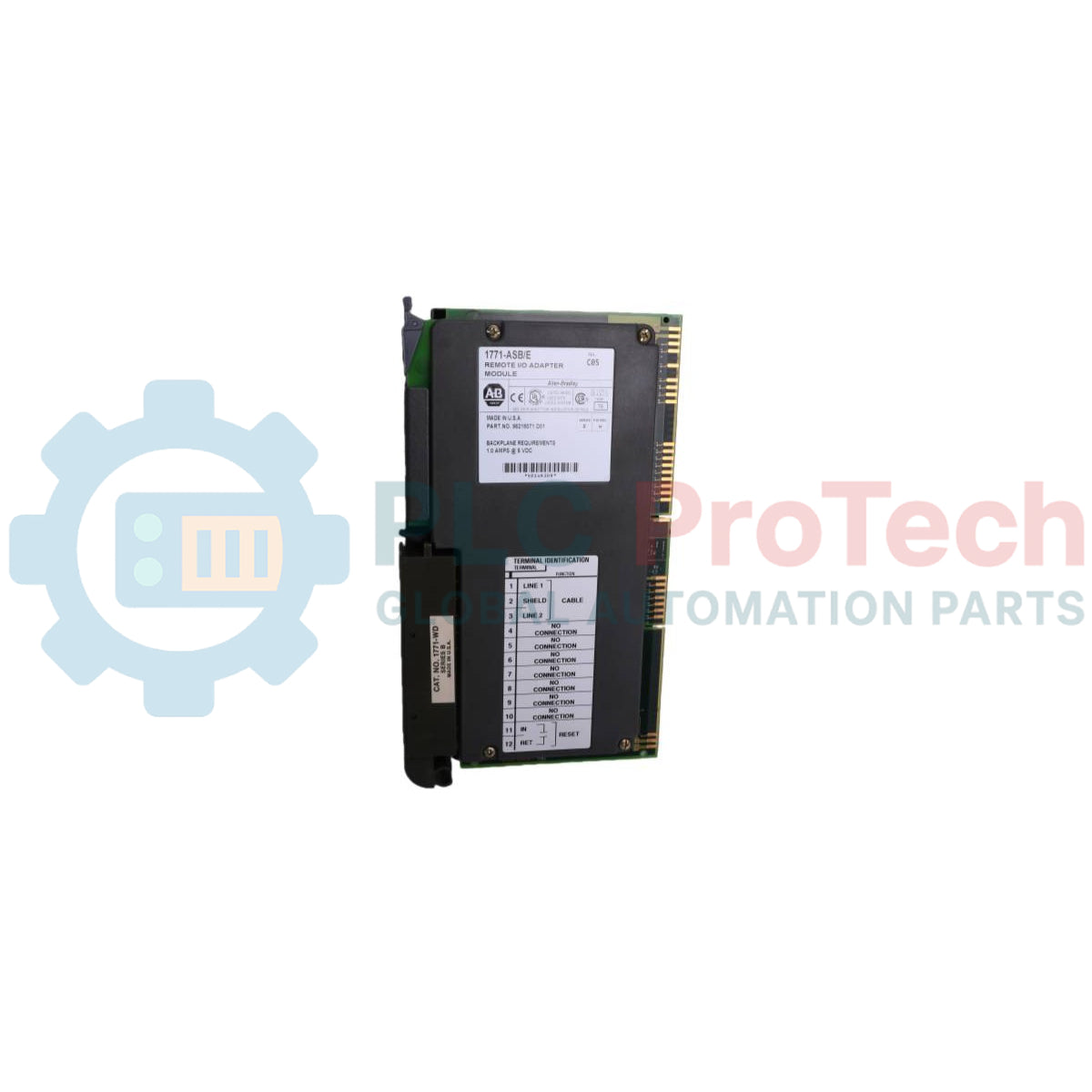
Allen-Bradley 1771-ASB/E Remote I/O Adapter Module

SKU 1771-ASB/E

Disponibile
  • 12-month warranty
  • Free returns within 30 days
  • Manufacturer: Allen-Bradley
  • Product No.: 1771-ASB/E
  • Origin United States
  • Barcode: 8537101190
  • Payment: T/T, Western Union
  • Weight: 0.9 kg
  • Dimensions: 3.5cm x 13cm x 14.5cm
  • Shipping port: Xiamen
  • Warranty: 12 months

Tags

Product Documentation

Technical Datasheet (PDF) Complete specifications and technical drawings.

Technical Datasheet

Allen-Bradley 1771-ASB/E Remote I/O Adapter Module

Quantità

Product Description

Description

The Allen-Bradley 1771-ASB/E is a remote I/O adapter module that serves as an interface between remote I/O modules and Allen-Bradley programmable controllers. The module receives and sends data from and to the I/O scanner in serial form, and reads and writes data from and to input and output modules in parallel form. It transmits data up to 10,000 cable-feet at 57.6K baud and provides backplane scanning and data transmission up to 2,500 cable-feet at 230.4K baud. The adapter supports any mix of 4, 6, 8, 16, or 32-point I/O modules and accommodates 1/2-slot, 1-slot, and 2-slot I/O addressing methods. It performs I/O configuration checks on power-up to verify module placement and scans all slots in the chassis or all but the last four slots. Additionally, it can emulate Series B adapters to provide system response compatible with 1771-S4A and 1771-S4B scanners.

Features

  • Transmits data up to 10,000 cable-feet at 57.6K baud and up to 2,500 cable-feet at 230.4K baud.
  • Supports 1/2-slot, 1-slot, and 2-slot I/O addressing modes.
  • Supports 4, 6, 8, 16, or 32-point discrete and block-transfer I/O modules.
  • Emulates Series B adapter link response for compatibility with PLC-2 and PLC-3 scanners.
  • Verifies I/O module placement on power-up.
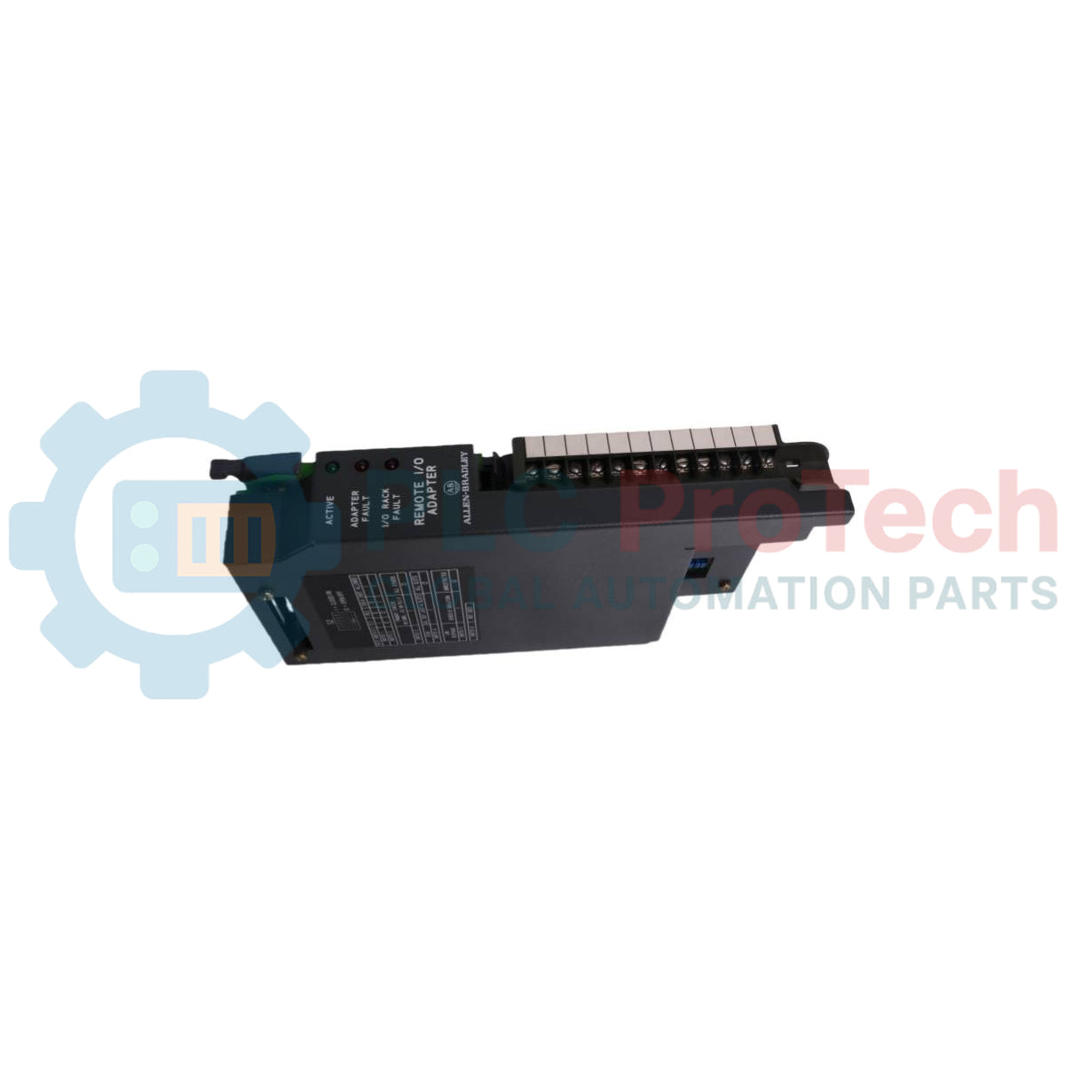
  • Features front-panel ACTIVE, ADAPTER FAULT, and I/O RACK FAULT LED diagnostic indicators.
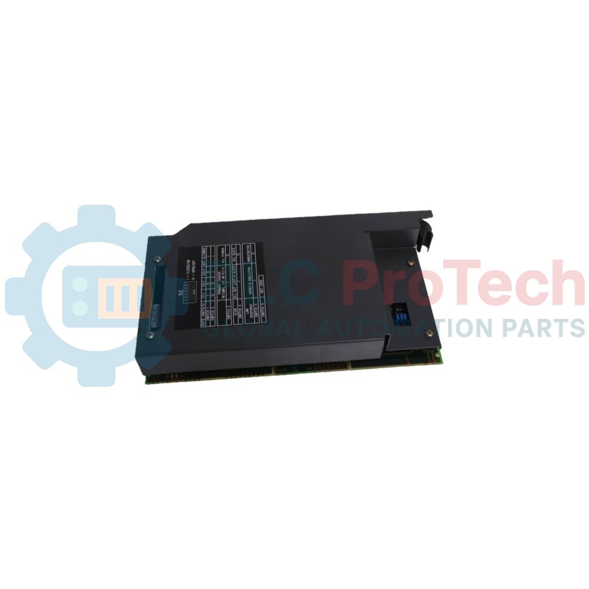
  • Includes backplane noise immunity retry options selectable via switch assembly.

Applications

  • Remote I/O chassis interfacing in Allen-Bradley PLC-2, PLC-3, and PLC-5 programmable controller systems.
  • Distributed industrial control architectures utilizing Universal I/O chassis.

Technical Specifications

Parameter Specification
Manufacturer Allen-Bradley
Catalog Number 1771-ASB Series E
Module Type Remote I/O Adapter Module
Backplane Current 1.0A at 5V DC
Transmission Distance / Baud Rate 10,000 cable-feet at 57.6K baud; 2,500 cable-feet at 230.4K baud
Supported Addressing Modes 1/2-slot, 1-slot, 2-slot
Supported I/O Densities 4, 6, 8, 16, 32 points
Compatible Wiring Arm 1771-WB

Connections/Interfaces

Terminal Pin Function
1 Blue (Remote I/O Cable)
2 Shield (Remote I/O Cable)
3 Clear (Remote I/O Cable)
4 Connected internally to Terminal 1
5 Connected internally to Terminal 2
6 Connected internally to Terminal 3
7 User-supplied I/O rack restart pushbutton
8 User-supplied I/O rack restart pushbutton

Installation Guidelines

  • Location & Keying: The 1771-ASB module must be installed in the leftmost slot of the I/O chassis. Key the backplane connectors using keying bands between pins 54–56 for the upper connector and pins 16–18 for the lower connector.
  • Power Precautions: Remove system power before inserting or removing the module from the I/O chassis to prevent potential circuitry damage.
  • 32-Point / Thermocouple Plug Selection: Access configuration plugs through the side access hole. Set plugs to the left position to enable 32-point I/O modules, or to the right position when using 1771-IX or 1771-IY thermocouple modules.
  • Module Mounting: Place the module in the plastic guide tracks of the leftmost slot, press firmly to seat it in the backplane connectors, and secure the chassis locking bar.
  • Termination: For the last adapter module on the link, connect a terminating resistor across terminals 1 (blue) and 3 (clear) on the field wiring arm (150 ohm standard, or 82 ohm for extended node capability at 230.4K baud).

Compliance and Certifications

  • CE Mark (Directive 89/336/EEC EMC: EN 50081-2, EN 50082-2; Low Voltage Directive 73/23/EEC: EN 61131-2)
Shipping & Returns

Global Express Shipping

  • Standard Delivery: 4–6 business days via DHL, FedEx, and UPS.
  • Express Dispatch: Same-day dispatch for in-stock orders placed before 2:00 PM (GMT+8).
  • Worldwide Coverage: Serving over 150 countries.

Returns & Warranty

  • 30-Day Guarantee: Returns accepted for in-stock products in original, factory-sealed packaging.
  • 12-Month Warranty: Every industrial component is backed by our technical warranty.
FAQ
What power is required from the chassis backplane for the communication module?
The module requires a backplane current of 1.0A at 5V DC.
Which slot in the I/O chassis must the module be installed in?
The module must always be installed in the leftmost slot of the I/O chassis.
What baud rates and cable distances does the adapter module support?
It supports data transmission up to 10,000 cable-feet at 57.6K baud and up to 2,500 cable-feet at 230.4K baud.
How are terminating resistors applied to the remote I/O link?
A terminating resistor must be connected across terminals 1 (blue) and 3 (clear) on the field wiring arm of the last adapter on the link.
Reviews

1771-ASB/E

Stock & lead time on request

Call
1 su 3

Allen-Bradley 1771-ASB/E Remote I/O Adapter Module

Only 5 item(s) left in stock
  • Manufacturer: Allen-Bradley

  • Product No.: 1771-ASB/E

  • Country of origin:United States

  • Barcode: 8537101190

  • Payment: T/T, Western Union

  • Weight: 900g

  • Dimensions: 3.5cm x 13cm x 14.5cm

  • Shipping port: Xiamen

  • Warranty: 12 months

Quantità
Visualizza dettagli completi

Product Description

Description

The Allen-Bradley 1771-ASB/E is a remote I/O adapter module that serves as an interface between remote I/O modules and Allen-Bradley programmable controllers. The module receives and sends data from and to the I/O scanner in serial form, and reads and writes data from and to input and output modules in parallel form. It transmits data up to 10,000 cable-feet at 57.6K baud and provides backplane scanning and data transmission up to 2,500 cable-feet at 230.4K baud. The adapter supports any mix of 4, 6, 8, 16, or 32-point I/O modules and accommodates 1/2-slot, 1-slot, and 2-slot I/O addressing methods. It performs I/O configuration checks on power-up to verify module placement and scans all slots in the chassis or all but the last four slots. Additionally, it can emulate Series B adapters to provide system response compatible with 1771-S4A and 1771-S4B scanners.

Features

  • Transmits data up to 10,000 cable-feet at 57.6K baud and up to 2,500 cable-feet at 230.4K baud.
  • Supports 1/2-slot, 1-slot, and 2-slot I/O addressing modes.
  • Supports 4, 6, 8, 16, or 32-point discrete and block-transfer I/O modules.
  • Emulates Series B adapter link response for compatibility with PLC-2 and PLC-3 scanners.
  • Verifies I/O module placement on power-up.
  • Features front-panel ACTIVE, ADAPTER FAULT, and I/O RACK FAULT LED diagnostic indicators.
  • Includes backplane noise immunity retry options selectable via switch assembly.

Applications

  • Remote I/O chassis interfacing in Allen-Bradley PLC-2, PLC-3, and PLC-5 programmable controller systems.
  • Distributed industrial control architectures utilizing Universal I/O chassis.

Technical Specifications

Parameter Specification
Manufacturer Allen-Bradley
Catalog Number 1771-ASB Series E
Module Type Remote I/O Adapter Module
Backplane Current 1.0A at 5V DC
Transmission Distance / Baud Rate 10,000 cable-feet at 57.6K baud; 2,500 cable-feet at 230.4K baud
Supported Addressing Modes 1/2-slot, 1-slot, 2-slot
Supported I/O Densities 4, 6, 8, 16, 32 points
Compatible Wiring Arm 1771-WB

Connections/Interfaces

Terminal Pin Function
1 Blue (Remote I/O Cable)
2 Shield (Remote I/O Cable)
3 Clear (Remote I/O Cable)
4 Connected internally to Terminal 1
5 Connected internally to Terminal 2
6 Connected internally to Terminal 3
7 User-supplied I/O rack restart pushbutton
8 User-supplied I/O rack restart pushbutton

Installation Guidelines

  • Location & Keying: The 1771-ASB module must be installed in the leftmost slot of the I/O chassis. Key the backplane connectors using keying bands between pins 54–56 for the upper connector and pins 16–18 for the lower connector.
  • Power Precautions: Remove system power before inserting or removing the module from the I/O chassis to prevent potential circuitry damage.
  • 32-Point / Thermocouple Plug Selection: Access configuration plugs through the side access hole. Set plugs to the left position to enable 32-point I/O modules, or to the right position when using 1771-IX or 1771-IY thermocouple modules.
  • Module Mounting: Place the module in the plastic guide tracks of the leftmost slot, press firmly to seat it in the backplane connectors, and secure the chassis locking bar.
  • Termination: For the last adapter module on the link, connect a terminating resistor across terminals 1 (blue) and 3 (clear) on the field wiring arm (150 ohm standard, or 82 ohm for extended node capability at 230.4K baud).

Compliance and Certifications

  • CE Mark (Directive 89/336/EEC EMC: EN 50081-2, EN 50082-2; Low Voltage Directive 73/23/EEC: EN 61131-2)

Product Documentation

Technical Datasheet (PDF) Complete specifications and technical drawings.

Technical Datasheet

Allen-Bradley 1771-ASB/E Remote I/O Adapter Module

What power is required from the chassis backplane for the communication module?

The module requires a backplane current of 1.0A at 5V DC.

Which slot in the I/O chassis must the module be installed in?

The module must always be installed in the leftmost slot of the I/O chassis.

What baud rates and cable distances does the adapter module support?

It supports data transmission up to 10,000 cable-feet at 57.6K baud and up to 2,500 cable-feet at 230.4K baud.

How are terminating resistors applied to the remote I/O link?

A terminating resistor must be connected across terminals 1 (blue) and 3 (clear) on the field wiring arm of the last adapter on the link.

Global Express Shipping

  • Standard Delivery: 4-6 Business Days via DHL, FedEx, and UPS.
  • Express Dispatch: Same-day dispatch for in-stock orders placed before 2:00 PM (GMT+8).
  • Worldwide Coverage: Serving over 150 countries, including rapid delivery to Saudi Arabia and UAE.

Returns & Warranty

  • 30-Day Guarantee: Returns accepted for in-stock products in original, factory-sealed packaging.
  • 12-Month Warranty: Every industrial component is backed by our professional technical warranty.

Orders are processed and delivered Monday-Friday (excluding public holidays).


For full eligibility, restocking fees, and international return details, please view our official Refund & Return Policy .

TECHNICAL SPECIFICATIONS

Color pattern
Black
Country of origin
United States
Power source
DC Power

Technical knowledge

1756-L73 Firmware Upgrade Guide: v19 vs v21/v31 Decision

Replacing a 1756-L73 does not automatically mean upgrading its firmware. This guide compares v19.013, v21.011 and v31.011, focusing on project compatibility, HMI communications, legacy networks and...

Implementing 3-Switch XOR Ladder Logic with Internal Bit

Implement a 3-SPST switch XOR light circuit in LogixPro or RSLogix 500 using an internal relay bit. Includes truth tables, boolean equations, and verified.

Building a Modbus RTU Network with CompactLogix and DeltaV

Integrate Allen-Bradley CompactLogix, Caterpillar ATS, and generators into DeltaV DCS over Modbus RTU. Covers ProSoft MVI69-MCM, Miille DIN266 gateways.

ONS Instruction Not Energizing OTE in Studio 5000 Ladder Logic

ONS instruction fires but the OTE coil never latches in Studio 5000 because the one-shot is only true for one scan. Use OTL/OTU or seal-in logic instead.

Kinetix 5500 EtherNet/IP Network Switch Requirements and Topology

Configure Allen-Bradley Kinetix 5500 servo drives on EtherNet/IP. Covers CIP Sync, IEEE 1588 V2 timing, Stratix selection, DLR topology, and HMI.

Moving Average Filtering in DCS and PLC Analog Control

A moving-average filter is the sliding-window smoother most instrument engineers drop into DCS and PLC analog paths. Here is how the window works, how N and sample time set lag, and when a...