


Tutto sui PLC: la CPU
A practical engineering guide to PLC CPU operation, from deterministic scan cycles and I/O image tables to memory, communications, diagnostics, redundancy, processor sizing, and reliable system...


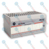
The 1794-OE12 is a high-density analog output module designed for the FLEX I/O distributed I/O platform. This hardware component functions as a multi-channel signal generator that converts digital data words from a central system controller into standardized analog current or voltage outputs. Operating at high channel density, the unit provides twelve single-ended output paths within a narrow modular layout, reducing physical footprint requirements inside remote electrical control panels.
Configurable per channel, the device drives variable-speed motor controllers, proportional control valves, industrial actuators, and chart recorders across distributed networks. The 1794-OE12 interfaces with host programmable automation controllers via local FLEX I/O adapters communicating over EtherNet/IP, ControlNet, or DeviceNet system networks. The module plugs directly into standard pre-wired terminal base units, securing backplane connections to the FlexBus automatically for reliable use in water treatment systems, chemical processing, paper mills, and material manipulation facilities.
| Parameter | Specification |
|---|---|
| Manufacturer | Rockwell Automation / Allen-Bradley |
| Brand | FLEX I/O |
| Part Number | 1794-OE12 |
| Module Type | High-Density Analog Output Module |
| Number of Outputs | 12 Channels, Single-Ended |
| Output Signal Ranges | 0 to 20 mA, 4 to 20 mA, +/-10V, 0 to 10V |
| Digital Resolution | 12-bit (320 uV/count Voltage, 4.88 uA/count Current) |
| Output Absolute Accuracy | 0.1% Full Scale at 25 Celsius |
| Output Accuracy Drift | 0.004% Full Scale per degC |
| External Power Supply Voltage | 24V DC Nominal |
| External Power Voltage Range | 10.0V DC to 31.2V DC (includes 5% AC ripple) |
| External Power Current Load | 320 mA at 24V DC, 720 mA at 10V DC |
| FlexBus Current Draw | 80 mA at 5V DC |
| Maximum Power Dissipation | 4.0 W at 31.2V DC |
| Maximum Thermal Dissipation | 4.7 BTU/hour at 24V DC |
| Maximum Resistive Load (Current) | 750 ohms at 24V DC |
| Minimum Resistive Load (Voltage) | 3.3 kilohms |
| Voltage Output Current Load | 3 mA maximum |
| Operating Temperature | 0 to 55 degC |
| Storage Temperature | -40 to 85 degC |
| Relative Humidity | 5% to 95% non-condensing |
| Operating Vibration | 5 g at 10 to 500 Hz per IEC 68-2-6 |
| Operating Shock | 30 g peak acceleration, 11 ms pulse width |
| Country of Origin | USA |
| Weight | 0.10 kg |
| Dimensions | 94.0 mm x 94.0 mm x 53.3 mm |
| Terminal Connection Node (1794-TB3G) | Function / Channel Allocation |
|---|---|
| Terminal 0 to Terminal 11 | Analog Output Signal Pins for Channels 0 through 11 |
| Terminal 16 to Terminal 27 | Analog Signal Return Common Paths (Return 0 to Return 11) |
| Terminal 36 / 37 | External +24V DC Primary Operational Power Intake |
| Terminal 38 / 39 | External DC Power Common Return Reference Nodes |
Hook the upper tracking slots on the back panel of the module housing onto the upper lip of standard 35 mm DIN tracking. Apply uniform downward and inward physical force until the spring-loaded lower metal retention tab snaps shut behind the bottom rail track.
Align the built-in structural plastic guide lines on the bottom interface of the operational module with the receiving socket grooves on the pre-wired terminal base unit (such as a 1794-TB3G or 1794-TB3GS). Push the electronic component directly into the interface socket until the latch ears click outward to lock it into place.
Execute all field loop connections using individual twisted shielded-pair instrumentation cables. Ground the overall copper braided drain shield wire at the functional chassis grounding terminals built into the terminal base assembly; do not ground both ends of the shield to prevent ground loops.
Isolate the low-voltage direct current analog output signaling cables away from electrical supply lines, direct current motor conductors, variable speed drive links, and inductive relay lines inside cabinet conduits to eliminate high-frequency noise injection.
What types of analog output parameters can this module generate?
It can be software-configured to generate standard current metrics like 4 to 20 mA and 0 to 20 mA, or voltage limits like 0 to 10V and +/-10V.
Does this device provide separate channel-to-channel electrical isolation?
No, the twelve independent output circuits are single-ended and reference a shared internal signal common line.
Can this unit be replaced while the system backplane remains powered?
Yes, it features removal and insertion under power attributes, allowing live field swaps without interrupting logic communication blocks on adjacent rail slots.
Which terminal base assemblies are approved for use with this device?
The module is engineered to be mounted on multi-point grounded terminal base blocks, specifically the 1794-TB3G or 1794-TB3GS units.
What happens to the output signals if communication with the controller drops?
The module can be configured via software to either hold its last valid output state or clear to a specific safe value when a network error occurs.
Is an external power supply connection required to run this module?
Yes, a nominal 24V DC external power supply loop must be run to the terminal base block to drive the internal digital-to-analog conversion circuits and power the field loops.
What is the continuous analog conversion resolution of the channels?
The unit converts internal logic registers into physical field outputs using a standard 12-bit digital-to-analog matrix structure.
What do the front-facing LED status indicators communicate to an engineer?
The light indicators provide real-time status diagnostics for the main operational state of the module and indicate external power availability.
What is the maximum electrical resistance threshold when operating in current mode?
The current loops can drive external loops with a total circuit resistive load up to a maximum parameter of 750 ohms at 24V DC.
How are the independent channel measurement parameters adjusted?
The required operational mode, range select values, and default state attributes are configured using the host PLC programming software environment.
Global Express Shipping
Returns & Warranty


Manufacturer: Allen-Bradley
Product No.: 1794-OE12
Country of origin:United States
Product Type: Analog Output Module
Barcode: 8537101190
Payment: T/T, Western Union
Weight: 900g
Dimensions: 3.5cm x 13cm x 14.5cm
Shipping port: Xiamen
Warranty: 12 months
The 1794-OE12 is a high-density analog output module designed for the FLEX I/O distributed I/O platform. This hardware component functions as a multi-channel signal generator that converts digital data words from a central system controller into standardized analog current or voltage outputs. Operating at high channel density, the unit provides twelve single-ended output paths within a narrow modular layout, reducing physical footprint requirements inside remote electrical control panels.
Configurable per channel, the device drives variable-speed motor controllers, proportional control valves, industrial actuators, and chart recorders across distributed networks. The 1794-OE12 interfaces with host programmable automation controllers via local FLEX I/O adapters communicating over EtherNet/IP, ControlNet, or DeviceNet system networks. The module plugs directly into standard pre-wired terminal base units, securing backplane connections to the FlexBus automatically for reliable use in water treatment systems, chemical processing, paper mills, and material manipulation facilities.
| Parameter | Specification |
|---|---|
| Manufacturer | Rockwell Automation / Allen-Bradley |
| Brand | FLEX I/O |
| Part Number | 1794-OE12 |
| Module Type | High-Density Analog Output Module |
| Number of Outputs | 12 Channels, Single-Ended |
| Output Signal Ranges | 0 to 20 mA, 4 to 20 mA, +/-10V, 0 to 10V |
| Digital Resolution | 12-bit (320 uV/count Voltage, 4.88 uA/count Current) |
| Output Absolute Accuracy | 0.1% Full Scale at 25 Celsius |
| Output Accuracy Drift | 0.004% Full Scale per degC |
| External Power Supply Voltage | 24V DC Nominal |
| External Power Voltage Range | 10.0V DC to 31.2V DC (includes 5% AC ripple) |
| External Power Current Load | 320 mA at 24V DC, 720 mA at 10V DC |
| FlexBus Current Draw | 80 mA at 5V DC |
| Maximum Power Dissipation | 4.0 W at 31.2V DC |
| Maximum Thermal Dissipation | 4.7 BTU/hour at 24V DC |
| Maximum Resistive Load (Current) | 750 ohms at 24V DC |
| Minimum Resistive Load (Voltage) | 3.3 kilohms |
| Voltage Output Current Load | 3 mA maximum |
| Operating Temperature | 0 to 55 degC |
| Storage Temperature | -40 to 85 degC |
| Relative Humidity | 5% to 95% non-condensing |
| Operating Vibration | 5 g at 10 to 500 Hz per IEC 68-2-6 |
| Operating Shock | 30 g peak acceleration, 11 ms pulse width |
| Country of Origin | USA |
| Weight | 0.10 kg |
| Dimensions | 94.0 mm x 94.0 mm x 53.3 mm |
| Terminal Connection Node (1794-TB3G) | Function / Channel Allocation |
|---|---|
| Terminal 0 to Terminal 11 | Analog Output Signal Pins for Channels 0 through 11 |
| Terminal 16 to Terminal 27 | Analog Signal Return Common Paths (Return 0 to Return 11) |
| Terminal 36 / 37 | External +24V DC Primary Operational Power Intake |
| Terminal 38 / 39 | External DC Power Common Return Reference Nodes |
Hook the upper tracking slots on the back panel of the module housing onto the upper lip of standard 35 mm DIN tracking. Apply uniform downward and inward physical force until the spring-loaded lower metal retention tab snaps shut behind the bottom rail track.
Align the built-in structural plastic guide lines on the bottom interface of the operational module with the receiving socket grooves on the pre-wired terminal base unit (such as a 1794-TB3G or 1794-TB3GS). Push the electronic component directly into the interface socket until the latch ears click outward to lock it into place.
Execute all field loop connections using individual twisted shielded-pair instrumentation cables. Ground the overall copper braided drain shield wire at the functional chassis grounding terminals built into the terminal base assembly; do not ground both ends of the shield to prevent ground loops.
Isolate the low-voltage direct current analog output signaling cables away from electrical supply lines, direct current motor conductors, variable speed drive links, and inductive relay lines inside cabinet conduits to eliminate high-frequency noise injection.
What types of analog output parameters can this module generate?
It can be software-configured to generate standard current metrics like 4 to 20 mA and 0 to 20 mA, or voltage limits like 0 to 10V and +/-10V.
Does this device provide separate channel-to-channel electrical isolation?
No, the twelve independent output circuits are single-ended and reference a shared internal signal common line.
Can this unit be replaced while the system backplane remains powered?
Yes, it features removal and insertion under power attributes, allowing live field swaps without interrupting logic communication blocks on adjacent rail slots.
Which terminal base assemblies are approved for use with this device?
The module is engineered to be mounted on multi-point grounded terminal base blocks, specifically the 1794-TB3G or 1794-TB3GS units.
What happens to the output signals if communication with the controller drops?
The module can be configured via software to either hold its last valid output state or clear to a specific safe value when a network error occurs.
Is an external power supply connection required to run this module?
Yes, a nominal 24V DC external power supply loop must be run to the terminal base block to drive the internal digital-to-analog conversion circuits and power the field loops.
What is the continuous analog conversion resolution of the channels?
The unit converts internal logic registers into physical field outputs using a standard 12-bit digital-to-analog matrix structure.
What do the front-facing LED status indicators communicate to an engineer?
The light indicators provide real-time status diagnostics for the main operational state of the module and indicate external power availability.
What is the maximum electrical resistance threshold when operating in current mode?
The current loops can drive external loops with a total circuit resistive load up to a maximum parameter of 750 ohms at 24V DC.
How are the independent channel measurement parameters adjusted?
The required operational mode, range select values, and default state attributes are configured using the host PLC programming software environment.
| Product Image | Model Number / Title | Condition | Availability | Action |
|---|---|---|---|---|
|
Allen-Bradley 1794-OA8I FLEX I/O 8-Point Isolated AC Digital Output Module | Original New | In Stock | View Details |
Global Express Shipping
Returns & Warranty
Orders are processed and delivered Monday-Friday (excluding public holidays).
For full eligibility, restocking fees, and international return details, please view our official Refund & Return Policy .
| Country of origin |
United States
|

A practical engineering guide to PLC CPU operation, from deterministic scan cycles and I/O image tables to memory, communications, diagnostics, redundancy, processor sizing, and reliable system...

Replacing a 1756-L73 does not automatically mean upgrading its firmware. This guide compares v19.013, v21.011 and v31.011, focusing on project compatibility, HMI communications, legacy networks and...

Implementa un circuito luminoso XOR con 3 interruttori SPST in LogixPro o RSLogix 500 utilizzando un bit di relè interno. Include tabelle della verità, equazioni booleane e verifica.

Integra Allen-Bradley CompactLogix, Caterpillar ATS e generatori nel DCS DeltaV tramite Modbus RTU. Include i gateway ProSoft MVI69-MCM e Miille DIN266.

L’istruzione ONS si attiva, ma la bobina OTE non rimane mai eccitata in Studio 5000 perché il one-shot è vero solo per una scansione. Usa OTL/OTU oppure una logica di autoritenuta.

Configura i servoazionamenti Allen-Bradley Kinetix 5500 su EtherNet/IP. Include CIP Sync, la temporizzazione IEEE 1588 V2, la selezione degli switch Stratix, la topologia DLR e l’HMI.