


Replacing a Beckhoff EL4032: Wiring and Output Checks
A field checklist for replacing a Beckhoff EL4032, covering the ±10 V load, terminal map, power contacts, EtherCAT state, and watchdog behavior.
Manufacturer: General Electric
Product No.: IC695PSA040
Country of origin:United States
Product Type: Alimentatore
Barcode: 8537101190
Payment: T/T, Western Union
Weight: 1200g
Dimensions: 3,5 cm x 13 cm x 13,5 cm
Shipping port: Xiamen
Warranty: 12 months
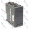
Il modulo IC695PSA040 (IC695PSA040) è un alimentatore ad alta efficienza da 40 watt progettato per la piattaforma GE PACSystems RX3i. Operando con intervalli universali di tensione in ingresso da 85 a 264 VAC o da 100 a 300 VDC, questo modulo distribuisce un'alimentazione stabile direttamente attraverso il backplane per alimentare le risorse locali di elaborazione e I/O. Le operazioni industriali all'interno di impianti automatizzati per il trattamento delle acque, strutture per la lavorazione chimica e linee di assemblaggio manifatturiere fanno affidamento sul IC695PSA040 (IC695PSA040) per garantire un'esecuzione prevedibile del controller in condizioni di alimentazione di rete fluttuanti. Il modulo di alimentazione isola l'elettronica interna del rack dai disturbi elettrici sul campo, registra i guasti predittivi direttamente nelle tabelle della CPU durante condizioni di stress termico o di carico e mantiene una capacità integrata di continuità operativa. Questa resilienza architetturale previene arresti improvvisi del PLC, protegge i parametri runtime critici e riduce significativamente i costosi tempi di inattività non pianificati dell'impianto.
La topologia hardware del modulo IC695PSA040 è incentrata sulla gestione localizzata dell'uscita a tripla linea di alimentazione e sulla protezione elettronica automatica.
Uscita a tripla linea di alimentazione: Fornisce in modo indipendente +5.1 VDC e +3.3 VDC per soddisfare i requisiti dei moduli a livello di sistema RX3i, oltre a un percorso di uscita relè dedicato da +24 VDC per alimentare i moduli relè di uscita esterni.
Controlli attivi della sovracorrente: Dispone di una limitazione elettronica della corrente integrata che limita la linea da 5.1 VDC a 7 A e quella da 3.3 VDC a 10 A. In caso di sovraccarico o cortocircuito, l'alimentatore si spegne automaticamente e avvia tentativi continui di riavvio automatico finché il guasto sul campo sottostante non viene eliminato.
Diagnostica completa dello stato: Integra una serie di quattro indicatori LED frontali dello stato, associati a relè diagnostici interni che trasmettono in tempo reale al registro dei guasti della CPU centrale informazioni su sovratemperatura, sovraccarico e stato dei componenti interni.
| Indice di progettazione | Specifica tecnica |
| Numero di modello | IC695PSA040 |
| Identificativo del marchio | GE PACSystems (General Electric) |
| Serie del sistema di controllo | Controller RX3i |
| Potenza di uscita nominale totale | 40 W massimi complessivi |
| Tensione nominale di ingresso | 120/240 V CA o 125 V CC |
| Intervallo di ingresso CA | Da 85 a 264 V CA |
| Intervallo di ingresso CC | Da 100 a 300 V CC |
| Potenza di ingresso massima | 70 W massimo a pieno carico |
| Soglia della corrente di spunto | 4 A per un massimo di 250 millisecondi |
| Specifiche della corrente di uscita | 5,1 V CC (da 0 a 6 A), 3,3 V CC (da 0 a 9 A), 24 V CC (da 0 a 1,6 A) |
| Limiti di tensione | 5,1 V CC (da 5,0 a 5,2 V CC), 3,3 V CC (da 3,1 a 3,5 V CC), 24 V CC (da 19,2 a 28,8 V CC) |
| Isolamento galvanico | 250 V CA continuo (1500 V CA per 1 minuto dall'ingresso al backplane) |
| Durata di mantenimento | Minimo 20 ms durante l'interruzione della sorgente |
| Intervallo di cablaggio sul campo | Un singolo filo da 14 AWG a 22 AWG per terminale |
| Capacità di collegamento a catena | Fino a 4 unità PSA040 |
| Limiti dell'aria di esercizio | Da 0 a 60 °C (temperatura ambiente esterna) |
| Codice di protezione ATEX | II 3 G Ex nA IIC T3C |
| Paese di origine | Stati Uniti |
L'alimentatore IC695PSA040 può essere configurato in parallelo per ottenere una ridondanza N+1?
No. Questo alimentatore specifico è progettato esclusivamente per il funzionamento autonomo all'interno di un backplane universale RX3i (serie di catalogo IC695). Non può essere abbinato ad altri alimentatori per aumentare la capacità del sistema o fornire ridondanza hardware. Il tentativo di utilizzare versioni precedenti (versione IC695PSA040C e precedenti) insieme a un altro alimentatore nello stesso slot del backplane può causare gravi danni alle apparecchiature.
Cosa fa passare l'indicatore LED di alimentazione principale da verde fisso ad ambra?
Una spia verde indica che il modulo è alimentato e sta fornendo correttamente tensioni CC stabili al backplane. Una spia ambra indica che l'alimentazione in ingresso è applicata correttamente ai morsetti di ingresso del modulo, ma l'interruttore a levetta sul pannello frontale è impostato su OFF, impedendo l'erogazione di alimentazione al rack.
Quali guasti sistemici sottostanti causano un arresto completo senza attivare un indicatore LED di guasto esterno?
Nella linea di ingresso è presente un collegamento fusibile interno non riparabile, che funge da protezione hardware finale. Sebbene il modulo attivi solitamente l'arresto elettronico prima che questo fusibile si guasti, un cortocircuito estremo di un componente interno o un'eccessiva sovratensione in ingresso possono interrompere permanentemente questo collegamento. Quando il fusibile si brucia, tutte le indicazioni operative cessano e il modulo deve essere sostituito fisicamente.
Mitigazione del rischio di scosse elettriche e sicurezza del comando ON/OFF:
Durante il funzionamento con una fonte di alimentazione CA, sulle strutture dei circuiti interni del modulo sono presenti tensioni pericolose (120 VAC o 240 VAC). Lo sportello anteriore di accesso ai terminali deve rimanere chiuso durante il normale funzionamento per prevenire il rischio di scosse mortali. Si noti che l'interruttore anteriore ON/OFF dietro lo sportello controlla solo gli stadi di uscita CC secondari; NON scollega l'alimentazione di rete in ingresso dai morsetti terminali.
Inserimento dei cavi e limiti di coppia:
Spellare tutti i conduttori dei terminali per una lunghezza minima compresa tra 9 mm e 11 mm. Assicurarsi che il filo sia inserito completamente nell'alloggiamento del terminale, fino a quando l'isolamento del conduttore non è a filo con il fermo di isolamento interno. Serrare con cautela i morsetti a vite, assicurandosi di non superare il limite massimo di coppia consentito di 0.5 N-m (4.4 inch-lbs). Un inserimento non corretto può causare il bloccaggio del morsetto a vite sull'isolamento del filo, provocando circuiti aperti o punti di terminazione surriscaldati.
Procedura per il ponticello di protezione dalle sovratensioni e i test Hi-pot:
I morsetti terminali inferiori contengono un circuito di protezione dalle sovratensioni con varistore all'ossido di metallo (MOV), che deve essere collegato alla terra del telaio tramite un ponticello installato dall'utente per fornire una protezione di base dalle sovratensioni in ingresso. Per eseguire un test dielettrico ad alto potenziale (Hi-pot) sull'alimentatore, è necessario disabilitare questo circuito di protezione dalle sovratensioni rimuovendo il ponticello. Reinstallare immediatamente il ponticello di terra al termine del test per ripristinare la protezione dai transitori.


Global Express Shipping
Returns & Warranty


| Product Image | Model Number / Title | Condition | Availability | Action |
|---|---|---|---|---|
|
Alimentatore Allen-Bradley 1746-P4 SLC 500 | Original New | In Stock | View Details |
Global Express Shipping
Returns & Warranty
Orders are processed and delivered Monday-Friday (excluding public holidays).
For full eligibility, restocking fees, and international return details, please view our official Refund & Return Policy .
| Color pattern |
Black
|
| Country of origin |
United States
|
| Power source |
AC-powered
|

A field checklist for replacing a Beckhoff EL4032, covering the ±10 V load, terminal map, power contacts, EtherCAT state, and watchdog behavior.

Before replacing a Yokogawa AAI835, verify the 4-in/4-out channel map, power-loss loop behavior, barrier type, output load, cable, and redundancy.

ABB PM891K01 article 3BSE053241R1 is the non-redundant AC 800M processor kit. Use this field checklist before replacement.

Replacement checks for ABB TP853 3BSE018126R1: identify the installed CI853, CI855, CI857, or CI861 interface, record wiring, and verify communication after installation.

Engineering checks for the Allen-Bradley 5069-L330ERMS2: controller capacity, separate RTB kits, local I/O limits, network-node limits, and motion-axis count.

Checks to record before replacing ABB 3HNE 00006-1 DSQC 351: controller generation, X3/X5/X20/X21 wiring, DeviceNet settings, INTERBUS mapping, and LED states.