Honeywell

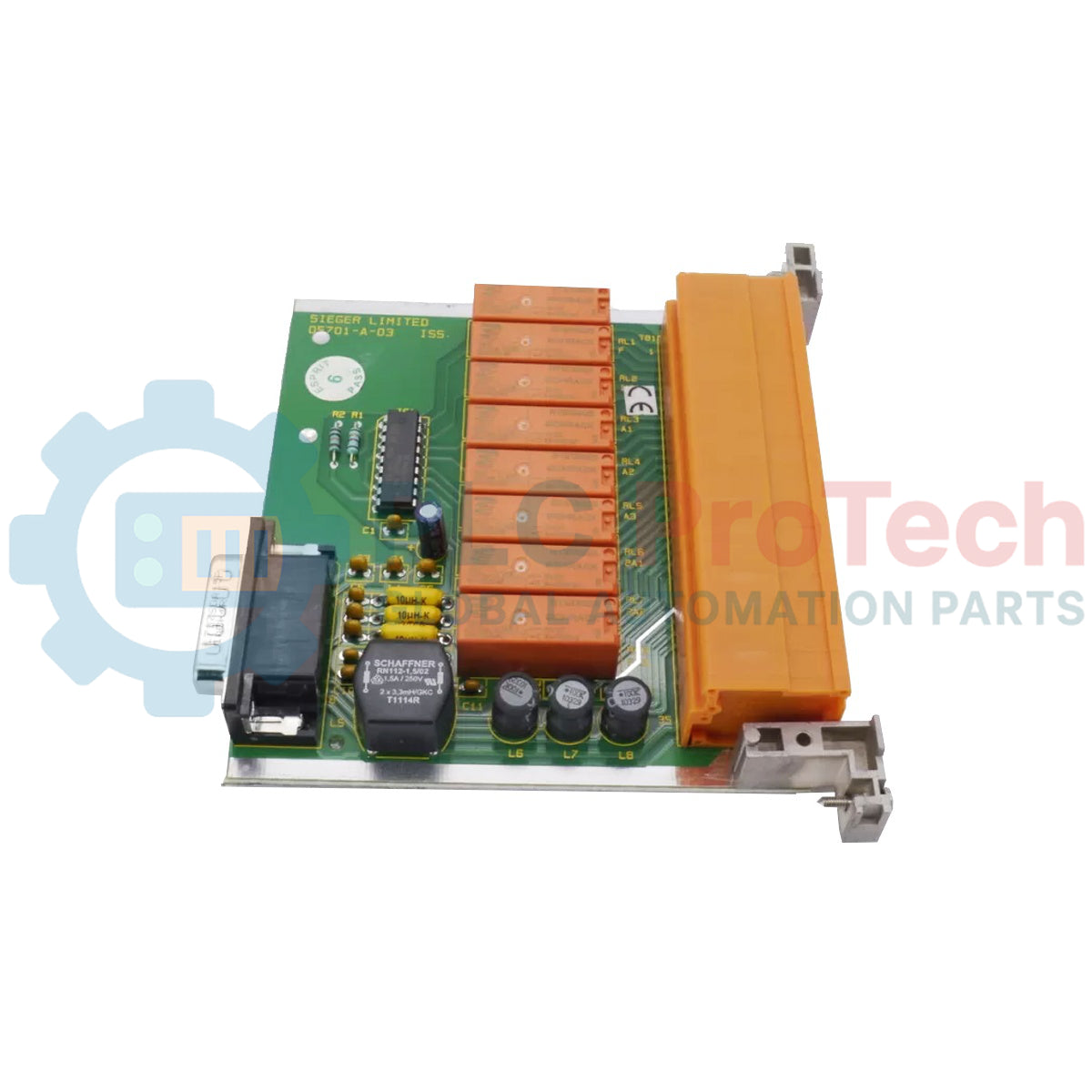
Honeywell 05701-A-0329 System 57 Triple DPCO Relay Card

SKU 05701-A-0329

Disponibile
  • 12-month warranty
  • Free returns within 30 days
  • Manufacturer: Honeywell
  • Product No.: 05701-A-0329
  • Origin United States
  • Product Type: Relay Interface Cards
  • Payment: T/T, Western Union
  • Weight: 2.5 kg
  • Dimensions: 170 mm x 130 mm x 30 mm (H x W x D)
  • Shipping port: Xiamen
  • Warranty: 12 months

Tags

Product Documentation

Technical Datasheet (PDF) Complete specifications and technical drawings.

Technical Datasheet

Honeywell 05701-A-0329 System 57 Triple DPCO Relay Card

Quantità

Product Description

Description

The Honeywell 05701-A-0329 functions as a high-integrity field interface and switching termination card inside the System 57 architecture. This device provides a dedicated electrical framework to link field-mounted gas detection sensors and active processing nodes with external alarm signaling, field indicators, or automatic process shutdown equipment.

The module incorporates three independent double-pole change-over (DPCO) electromechanical relays, configured to deliver voltage-free contact outputs based on localized danger thresholds. These onboard relay circuits are mapped directly across the common sub-rack backplane to mirror dedicated event parameters handled by the companion single-channel control cards, responding to A1 alarm, A2 alarm, and fault condition routines. Its physical design utilizes compression-style terminal execution to preserve low-resistance wiring continuity, facilitating signal integrity isolation and localized instrumentation shield grounding required within heavy manufacturing or processing installations.

Features

  • Features three high-density double-pole change-over (DPCO) electromechanical relays delivering dual-pole voltage-free contact operation.
  • Maps distinct hardware switching loops for three functional control parameters: A1 alarm level, A2 alarm level, and system fault condition validation.
  • Provides dedicated internal ground distribution tracks allowing structured instrumentation cable shield drain paths directly at the module level.
  • Structured in a standard 3U format compatible with System 57 backplane communications and standard rack power line footprints.
  • Incorporates rugged heavy-duty screw terminal blocks to maintain rigid wire retention under industrial vibration scenarios.

Applications

  • Multi-pole interlocking shutdown control loops requiring simultaneous isolation of redundant power and control paths during gas hazards.
  • Interfacing gas detection sub-racks with centralized safety instrumented systems (SIS) or critical plant distributed control systems (DCS).
  • Remote signaling management for high-capacity visual strobe arrays and audible sirens across petrochemical refineries or water treatment plants.

Technical Specifications

Parameter Specifications
Manufacturer Honeywell
Model Number 05701-A-0329
Product Type Triple DPCO Relay Card
Product Series System 57 / 5701 Series Control System
Contact Configuration Double Pole Change-Over (DPCO)
Relay Allocations A1 Alarm, A2 Alarm, Fault Condition
Maximum Switching Limit 5A maximum (under resistive AC mains switching loads)
Shipping Weight 2.5 Kg

Connections/Interfaces

Connector Terminal Function
Fault NC1 / NO1 / COM1 Fault Relay Pole 1 Normally Closed / Normally Open / Common Contacts
Fault NC2 / NO2 / COM2 Fault Relay Pole 2 Normally Closed / Normally Open / Common Contacts
A1 NC1 / NO1 / COM1 Alarm 1 Relay Pole 1 Normally Closed / Normally Open / Common Contacts
A1 NC2 / NO2 / COM2 Alarm 2 Relay Pole 2 Normally Closed / Normally Open / Common Contacts
A2 NC1 / NO1 / COM1 Alarm 2 Relay Pole 1 Normally Closed / Normally Open / Common Contacts
A2 NC2 / NO2 / COM2 Alarm 2 Relay Pole 2 Normally Closed / Normally Open / Common Contacts
Sensor S Sensor Supply Line Path
Sensor NS Sensor Non-Sink / Signal Input Path
Sensor 0V Sensor 0V Reference Line Path
GND Instrumentation Clean Earth Cable Shield Ground Terminal

Installation Guidelines

  • Fusing Regulations: Limit external circuit feeds routed through the relay contacts with an active inline 5A maximum safety fuse to shield internal module traces from overcurrent states.
  • Low-Impedance Earthing: Ensure a clean instrumentation grounding wire is bonded securely to the card ground terminals to facilitate proper drainage of ambient RFI/EMI.
  • Wiring Type and Terminations: Connect all field sensors and output interlocks using multi-conductor shielded instrumentation cable up to 2.5mm2, crimping raw ends with insulated ferrules before insertion.
  • Separation of Voltage Classes: Route low-voltage DC analog sensor lines through separate trunking conduits away from any high-voltage AC mains lines wired across the DPCO contacts.
  • Shield Continuity Management: Isolate the cable shielding path at the field device end if the transmitter housing is bolted directly to local earth-grounded infrastructure to block common-mode loop currents.
Shipping & Returns

Global Express Shipping

  • Standard Delivery: 4–6 business days via DHL, FedEx, and UPS.
  • Express Dispatch: Same-day dispatch for in-stock orders placed before 2:00 PM (GMT+8).
  • Worldwide Coverage: Serving over 150 countries.

Returns & Warranty

  • 30-Day Guarantee: Returns accepted for in-stock products in original, factory-sealed packaging.
  • 12-Month Warranty: Every industrial component is backed by our technical warranty.
FAQ
What is the Honeywell 05701-A-0329 used for?
The Honeywell 05701-A-0329 is a System 57 Triple DPCO Relay Card used as a field interface and switching termination card to link gas detection sensors and control nodes with external alarm signaling, field indicators, or process shutdown equipment.
Which product series does the card belong to?
The card belongs to the Honeywell System 57 / 5701 Series Control System.
What contact configuration do the onboard relays provide?
The card features three independent double-pole change-over (DPCO) electromechanical relays for A1 alarm, A2 alarm, and fault condition switching.
What is the maximum switching limit for the relay contacts?
The maximum switching limit is 5A maximum under resistive AC mains switching loads.
How are the fault relay contact states configured by default?
The onboard fault relay operates in a permanently energized configuration during normal safe operations, ensuring that any system power drop or module removal opens the contact to generate a fail-safe alert.
Reviews

05701-A-0329

Stock & lead time on request

Call
1 su 1

Honeywell 05701-A-0329 System 57 Triple DPCO Relay Card

Only 7 item(s) left in stock
  • Manufacturer: Honeywell

  • Product No.: 05701-A-0329

  • Country of origin:United States

  • Product Type: Relay Interface Cards

  • Payment: T/T, Western Union

  • Weight: 2500g

  • Dimensions: 170 mm x 130 mm x 30 mm (H x W x D)

  • Shipping port: Xiamen

  • Warranty: 12 months

Quantità
Visualizza dettagli completi

Product Description

Description

The Honeywell 05701-A-0329 functions as a high-integrity field interface and switching termination card inside the System 57 architecture. This device provides a dedicated electrical framework to link field-mounted gas detection sensors and active processing nodes with external alarm signaling, field indicators, or automatic process shutdown equipment.

The module incorporates three independent double-pole change-over (DPCO) electromechanical relays, configured to deliver voltage-free contact outputs based on localized danger thresholds. These onboard relay circuits are mapped directly across the common sub-rack backplane to mirror dedicated event parameters handled by the companion single-channel control cards, responding to A1 alarm, A2 alarm, and fault condition routines. Its physical design utilizes compression-style terminal execution to preserve low-resistance wiring continuity, facilitating signal integrity isolation and localized instrumentation shield grounding required within heavy manufacturing or processing installations.

Features

  • Features three high-density double-pole change-over (DPCO) electromechanical relays delivering dual-pole voltage-free contact operation.
  • Maps distinct hardware switching loops for three functional control parameters: A1 alarm level, A2 alarm level, and system fault condition validation.
  • Provides dedicated internal ground distribution tracks allowing structured instrumentation cable shield drain paths directly at the module level.
  • Structured in a standard 3U format compatible with System 57 backplane communications and standard rack power line footprints.
  • Incorporates rugged heavy-duty screw terminal blocks to maintain rigid wire retention under industrial vibration scenarios.

Applications

  • Multi-pole interlocking shutdown control loops requiring simultaneous isolation of redundant power and control paths during gas hazards.
  • Interfacing gas detection sub-racks with centralized safety instrumented systems (SIS) or critical plant distributed control systems (DCS).
  • Remote signaling management for high-capacity visual strobe arrays and audible sirens across petrochemical refineries or water treatment plants.

Technical Specifications

Parameter Specifications
Manufacturer Honeywell
Model Number 05701-A-0329
Product Type Triple DPCO Relay Card
Product Series System 57 / 5701 Series Control System
Contact Configuration Double Pole Change-Over (DPCO)
Relay Allocations A1 Alarm, A2 Alarm, Fault Condition
Maximum Switching Limit 5A maximum (under resistive AC mains switching loads)
Shipping Weight 2.5 Kg

Connections/Interfaces

Connector Terminal Function
Fault NC1 / NO1 / COM1 Fault Relay Pole 1 Normally Closed / Normally Open / Common Contacts
Fault NC2 / NO2 / COM2 Fault Relay Pole 2 Normally Closed / Normally Open / Common Contacts
A1 NC1 / NO1 / COM1 Alarm 1 Relay Pole 1 Normally Closed / Normally Open / Common Contacts
A1 NC2 / NO2 / COM2 Alarm 2 Relay Pole 2 Normally Closed / Normally Open / Common Contacts
A2 NC1 / NO1 / COM1 Alarm 2 Relay Pole 1 Normally Closed / Normally Open / Common Contacts
A2 NC2 / NO2 / COM2 Alarm 2 Relay Pole 2 Normally Closed / Normally Open / Common Contacts
Sensor S Sensor Supply Line Path
Sensor NS Sensor Non-Sink / Signal Input Path
Sensor 0V Sensor 0V Reference Line Path
GND Instrumentation Clean Earth Cable Shield Ground Terminal

Installation Guidelines

  • Fusing Regulations: Limit external circuit feeds routed through the relay contacts with an active inline 5A maximum safety fuse to shield internal module traces from overcurrent states.
  • Low-Impedance Earthing: Ensure a clean instrumentation grounding wire is bonded securely to the card ground terminals to facilitate proper drainage of ambient RFI/EMI.
  • Wiring Type and Terminations: Connect all field sensors and output interlocks using multi-conductor shielded instrumentation cable up to 2.5mm2, crimping raw ends with insulated ferrules before insertion.
  • Separation of Voltage Classes: Route low-voltage DC analog sensor lines through separate trunking conduits away from any high-voltage AC mains lines wired across the DPCO contacts.
  • Shield Continuity Management: Isolate the cable shielding path at the field device end if the transmitter housing is bolted directly to local earth-grounded infrastructure to block common-mode loop currents.

Product Documentation

Technical Datasheet (PDF) Complete specifications and technical drawings.

Technical Datasheet

Honeywell 05701-A-0329 System 57 Triple DPCO Relay Card

What is the Honeywell 05701-A-0329 used for?

The Honeywell 05701-A-0329 is a System 57 Triple DPCO Relay Card used as a field interface and switching termination card to link gas detection sensors and control nodes with external alarm signaling, field indicators, or process shutdown equipment.

Which product series does the card belong to?

The card belongs to the Honeywell System 57 / 5701 Series Control System.

What contact configuration do the onboard relays provide?

The card features three independent double-pole change-over (DPCO) electromechanical relays for A1 alarm, A2 alarm, and fault condition switching.

What is the maximum switching limit for the relay contacts?

The maximum switching limit is 5A maximum under resistive AC mains switching loads.

How are the fault relay contact states configured by default?

The onboard fault relay operates in a permanently energized configuration during normal safe operations, ensuring that any system power drop or module removal opens the contact to generate a fail-safe alert.

Global Express Shipping

  • Standard Delivery: 4-6 Business Days via DHL, FedEx, and UPS.
  • Express Dispatch: Same-day dispatch for in-stock orders placed before 2:00 PM (GMT+8).
  • Worldwide Coverage: Serving over 150 countries, including rapid delivery to Saudi Arabia and UAE.

Returns & Warranty

  • 30-Day Guarantee: Returns accepted for in-stock products in original, factory-sealed packaging.
  • 12-Month Warranty: Every industrial component is backed by our professional technical warranty.

Orders are processed and delivered Monday-Friday (excluding public holidays).


For full eligibility, restocking fees, and international return details, please view our official Refund & Return Policy .

TECHNICAL SPECIFICATIONS

Color pattern
Green
Country of origin
United States
Power source
AC-powered

Technical knowledge

Tutto sui PLC: la CPU

A practical engineering guide to PLC CPU operation, from deterministic scan cycles and I/O image tables to memory, communications, diagnostics, redundancy, processor sizing, and reliable system...

Guida all’aggiornamento del firmware 1756-L73: scelta tra v19 e v21/v31

Sostituire un 1756-L73 non significa automaticamente aggiornare il firmware. Questa guida confronta le versioni 19.013, 21.011 e 31.011, concentrandosi sulla compatibilità dei progetti, sulle...

Implementazione della logica a scala XOR con 3 interruttori e bit interno

Implementa un circuito luminoso XOR con 3 interruttori SPST in LogixPro o RSLogix 500 utilizzando un bit di relè interno. Include tabelle della verità, equazioni booleane e verifica.

Creazione di una rete Modbus RTU con CompactLogix e DeltaV

Integra Allen-Bradley CompactLogix, Caterpillar ATS e generatori nel DCS DeltaV tramite Modbus RTU. Include i gateway ProSoft MVI69-MCM e Miille DIN266.

Istruzione ONS che non attiva l’OTE nella logica ladder di Studio 5000

L’istruzione ONS si attiva, ma la bobina OTE non rimane mai eccitata in Studio 5000 perché il one-shot è vero solo per una scansione. Usa OTL/OTU oppure una logica di autoritenuta.

Requisiti e topologia dello switch di rete EtherNet/IP Kinetix 5500

Configura i servoazionamenti Allen-Bradley Kinetix 5500 su EtherNet/IP. Include CIP Sync, la temporizzazione IEEE 1588 V2, la selezione degli switch Stratix, la topologia DLR e l’HMI.