Honeywell

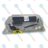
Honeywell CC-TDOR11 51308378-175 Rev A1 Experion Series C Digital Output Relay IOTA Redundant 12-Inch

SKU CC-TDOR11 51308378-175

Disponibile
  • 12-month warranty
  • Free returns within 30 days
  • Manufacturer: Honeywell
  • Product No.: CC-TDOR11 51308378-175
  • Origin United States
  • Product Type: Digital Output Relay IOTA
  • Barcode: 8537101190
  • Payment: T/T, Western Union
  • Weight: 0.85 kg
  • Dimensions: 305 x 125 x 65 mm
  • Shipping port: Xiamen
  • Warranty: 12 months

Tags

Product Documentation

Technical Datasheet (PDF) Complete specifications and technical drawings.

Technical Datasheet

Honeywell CC-TDOR11 51308378-175 Rev A1 Experion Series C Digital Output Relay IOTA Redundant 12-Inch

Quantità

Product Description

Description

The Honeywell CC-TDOR11 (Part Number 51308378-175 Rev A1) is a 12-inch Redundant Digital Output Relay Input Output Termination Assembly (IOTA) designed for the Honeywell Experion Series C process automation system. Functioning as an integral field termination platform for the C300 Controller architecture, it provides the physical termination point, signal routing, and power distribution for 32-channel digital output relay operations. By combining field wiring connections and electronic module mounting into a single chassis-less footprint, the CC-TDOR11 eliminates the requirement for separate card cages or rack chassis in cabinet layouts.

Engineered with conformally coated printed wiring boards (indicated by the CC prefix), the Honeywell CC-TDOR11 offers high environmental protection against harsh, corrosive, or industrial atmosphere contaminants. The IOTA operates with the CC-PDOB01 digital output module to drive up to 32 isolated dry contacts (Form A SPST/NO or Form B SPST/NC, jumper selectable per channel). Designed for high-reliability process control applications, it supports dual-channel redundant configurations to ensure uninterrupted switching execution across critical final control elements.

Features

  • Redundant Architecture: Serves as a 12-inch redundant IOTA assembly enabling high-availability digital output operations paired with Series C control hardware.
  • Chassis-less Series C Form Factor: Direct mount design combines field termination and module interface in one compact layout, eliminating extra rack chassis hardware.
  • 32-Channel Relay Interface: Designed to support 32 field-isolated digital outputs using Form A (Normally Open) or Form B (Normally Closed) dry contacts selectable via channel jumpers.
  • Conformal Coating Protection: Features factory conformally coated circuit assemblies for enhanced durability in harsh chemical and industrial environments.
  • Wide Load Voltage & Switching Capability: Accommodates switching control for loads up to 250 VAC (RMS) or 125 VDC across both resistive and inductive industrial field loops.
  • High Galvanic Isolation: Provides 1500 VAC RMS or ±1500 VDC electrical isolation between field circuitry and system internal logic.

Applications

  • Process Final Control Element Switching: Interfacing C300 control systems to interposing relays, solenoid valves, motor starters, and field annunciator panels.
  • Emergency Shutdown (ESD) & Safety Interlocks: Executing discrete power contact separation and fail-safe relay switching in critical safety shutdown loops.
  • High-Voltage Load Isolation: Galvanically separating sensitive 24 VDC control system electronics from high-voltage AC/DC field equipment.
  • Industrial Plant Automation: Deployed across continuous process plants including chemical refining, power generation, oil and gas processing, and industrial utilities.

Technical Specifications

General

Parameter Specification
Manufacturer Honeywell
Model Number CC-TDOR11
Part Number 51308378-175 Rev A1
Product Type Digital Output Relay IOTA (Input Output Termination Assembly)
System Platform Experion Series C / C300 Controller
Redundancy Support Redundant (12-Inch Assembly)
Coating Type Conformal Coated (CC)
Compatible Output Module CC-PDOB01

Output Capabilities & Relay Contacts

Parameter Specification
Output Channels 32 isolated Form A (SPST/NO) or Form B (SPST/NC) dry contacts (jumper selectable per output)
Maximum Load Voltage 250 VAC (RMS) / 125 VDC
Maximum Steady State Current (3 A / 250 VAC) 3 A (Resistive)
Maximum Steady State Current (3 A / 125 VAC) 3 A (Resistive)
Maximum Steady State Current (3 A / 30 VDC) 3 A (Resistive)
Maximum Steady State Current (1 A / 48 VDC) 1 A (Resistive)
Maximum Steady State Current (0.2 A / 125 VDC) 0.2 A (Resistive)
Maximum Steady State Current (2 A / 250 VAC) 2 A (Inductive – 0.4 power factor)
Maximum Steady State Current (2 A / 125 VAC) 2 A (Inductive – 0.4 power factor)
Maximum Steady State Current (1 A / 30 VAC) 1 A (Inductive L/R = 100 ms)
Maximum Steady State Current (0.3 A / 48 VAC) 0.3 A (Inductive L/R = 100 ms)
Maximum Steady State Current (0.1 A / 125 VAC) 0.1 A (Inductive L/R = 100 ms)
Minimum Load Voltage 5 VDC (valid if contact not previously used in high current/voltage applications)
Minimum Load Current 10 mA (valid if contact not previously used in high current/voltage applications)
Turn-On Time 20 ms maximum
Turn-Off Time 20 ms maximum
Mechanical Life 10,000,000 operations
Electrical Contact Life 200,000 operations @ 3 A (100% max load)

Isolation & Electrical Protection

Parameter Specification
Galvanic Isolation 1500 VAC RMS or ±1500 VDC
Channel Resistance Increment 120 ohms + 0.03 degF for each channel

Connections / Interfaces

Interface / Component Function
IOM Module Interface Direct plug-in mounting sockets for dual Series C Digital Output Modules
Channel Jumper Blocks Selectable jumpers per output channel to set Form A (NO) or Form B (NC) contact state
Field Termination Block Screw/clamp terminal points for field switching loops (250 VAC / 125 VDC max)
Power / System Bus Direct backplane/carrier integration for 24 VDC system distribution and control communications

Installation Guidelines

  1. Pre-Installation Inspection: Verify the part number (51308378-175 Rev A1) and check the assembly for physical damage before mounting into the cabinet assembly.
  2. Mounting: Secure the 12-inch CC-TDOR11 IOTA onto the standard Series C carrier channel within the control cabinet. Ensure adequate clearance for module plug-in and field wiring routing.
  3. Contact Form Selection: Configure channel jumpers on the IOTA prior to field connection to select either Form A (Normally Open) or Form B (Normally Closed) operation for each individual output channel.
  4. Field Wiring Connection: Connect field switching wires to designated IOTA terminals. Ensure field supply voltages do not exceed 250 VAC RMS or 125 VDC.
  5. Grounding & Isolation Verification: Confirm field wiring maintains galvanic isolation requirements (up to 1500 VAC RMS / ±1500 VDC) between external power sources and system common.
  6. Module Insertion: Carefully seat the digital output module onto the IOTA connector header until fully latched.

Commissioning & Replacement Recommendations

  • Parameter & Configuration Backup: Save control strategy configurations in Experion PKS prior to replacing or upgrading IOTA hardware.
  • Low-Level Contact Switching Note: If a relay contact channel has previously switched high-voltage or high-current loads, do not reuse that specific channel for low-level switching (5 VDC / 10 mA) due to potential contact surface alterations.
  • Redundant Switchover Testing: Verify smooth redundant switchover capability across both module slots under nominal 24 VDC power conditions prior to placing output channels online.
  • Maintenance Checks: Periodically perform operational contact tests to track mechanical contact life cycles under high inductive load operations.
Shipping & Returns

Global Express Shipping

  • Standard Delivery: 4–6 business days via DHL, FedEx, and UPS.
  • Express Dispatch: Same-day dispatch for in-stock orders placed before 2:00 PM (GMT+8).
  • Worldwide Coverage: Serving over 150 countries.

Returns & Warranty

  • 30-Day Guarantee: Returns accepted for in-stock products in original, factory-sealed packaging.
  • 12-Month Warranty: Every industrial component is backed by our technical warranty.
FAQ
What is the function of the Honeywell CC-TDOR11 51308378-175 Rev A1 in an Experion system?
The Honeywell CC-TDOR11 51308378-175 Rev A1 is a 12-inch redundant Input Output Termination Assembly (IOTA) for Experion Series C control systems. It provides physical field wiring terminations and mounting interfaces for 32 isolated digital output relay channels, routing signal control from the C300 Controller to external devices.
How are contact output types configured on the Honeywell CC-TDOR11 module?
Each of the 32 channels on the Honeywell CC-TDOR11 IOTA can be individually configured as Form A (SPST Normally Open) or Form B (SPST Normally Closed) dry contacts using physical jumpers located directly on the termination assembly.
What load switching ratings are supported by the Honeywell CC-TDOR11 digital output relay assembly?
The Honeywell CC-TDOR11 assembly supports maximum load voltages up to 250 VAC RMS and 125 VDC. It handles steady-state resistive currents up to 3 A at 250 VAC / 125 VAC / 30 VDC, and inductive loads up to 2 A at 250 VAC.
Can low-voltage low-current loads be switched on the Honeywell CC-TDOR11 relay channels?
The Honeywell CC-TDOR11 supports minimum load conditions down to 5 VDC and 10 mA, provided the output contact channel has not been previously used for high-current or high-voltage load switching.
What is the difference between CC-TDOR11 and CU-TDOR11 model numbers?
The CC prefix in CC-TDOR11 indicates that the printed circuit boards are conformally coated for corrosion and environmental protection, whereas the CU prefix denotes an uncoated assembly.
Reviews

CC-TDOR11 51308378-175

Stock & lead time on request

Call
1 su 3

Honeywell CC-TDOR11 51308378-175 Rev A1 Experion Series C Digital Output Relay IOTA Redundant 12-Inch

Only 2 item(s) left in stock
  • Manufacturer: Honeywell

  • Product No.: CC-TDOR11 51308378-175

  • Country of origin:United States

  • Product Type: Digital Output Relay IOTA

  • Barcode: 8537101190

  • Payment: T/T, Western Union

  • Weight: 850g

  • Dimensions: 305 x 125 x 65 mm

  • Shipping port: Xiamen

  • Warranty: 12 months

Quantità
Visualizza dettagli completi

Product Description

Description

The Honeywell CC-TDOR11 (Part Number 51308378-175 Rev A1) is a 12-inch Redundant Digital Output Relay Input Output Termination Assembly (IOTA) designed for the Honeywell Experion Series C process automation system. Functioning as an integral field termination platform for the C300 Controller architecture, it provides the physical termination point, signal routing, and power distribution for 32-channel digital output relay operations. By combining field wiring connections and electronic module mounting into a single chassis-less footprint, the CC-TDOR11 eliminates the requirement for separate card cages or rack chassis in cabinet layouts.

Engineered with conformally coated printed wiring boards (indicated by the CC prefix), the Honeywell CC-TDOR11 offers high environmental protection against harsh, corrosive, or industrial atmosphere contaminants. The IOTA operates with the CC-PDOB01 digital output module to drive up to 32 isolated dry contacts (Form A SPST/NO or Form B SPST/NC, jumper selectable per channel). Designed for high-reliability process control applications, it supports dual-channel redundant configurations to ensure uninterrupted switching execution across critical final control elements.

Features

  • Redundant Architecture: Serves as a 12-inch redundant IOTA assembly enabling high-availability digital output operations paired with Series C control hardware.
  • Chassis-less Series C Form Factor: Direct mount design combines field termination and module interface in one compact layout, eliminating extra rack chassis hardware.
  • 32-Channel Relay Interface: Designed to support 32 field-isolated digital outputs using Form A (Normally Open) or Form B (Normally Closed) dry contacts selectable via channel jumpers.
  • Conformal Coating Protection: Features factory conformally coated circuit assemblies for enhanced durability in harsh chemical and industrial environments.
  • Wide Load Voltage & Switching Capability: Accommodates switching control for loads up to 250 VAC (RMS) or 125 VDC across both resistive and inductive industrial field loops.
  • High Galvanic Isolation: Provides 1500 VAC RMS or ±1500 VDC electrical isolation between field circuitry and system internal logic.

Applications

  • Process Final Control Element Switching: Interfacing C300 control systems to interposing relays, solenoid valves, motor starters, and field annunciator panels.
  • Emergency Shutdown (ESD) & Safety Interlocks: Executing discrete power contact separation and fail-safe relay switching in critical safety shutdown loops.
  • High-Voltage Load Isolation: Galvanically separating sensitive 24 VDC control system electronics from high-voltage AC/DC field equipment.
  • Industrial Plant Automation: Deployed across continuous process plants including chemical refining, power generation, oil and gas processing, and industrial utilities.

Technical Specifications

General

Parameter Specification
Manufacturer Honeywell
Model Number CC-TDOR11
Part Number 51308378-175 Rev A1
Product Type Digital Output Relay IOTA (Input Output Termination Assembly)
System Platform Experion Series C / C300 Controller
Redundancy Support Redundant (12-Inch Assembly)
Coating Type Conformal Coated (CC)
Compatible Output Module CC-PDOB01

Output Capabilities & Relay Contacts

Parameter Specification
Output Channels 32 isolated Form A (SPST/NO) or Form B (SPST/NC) dry contacts (jumper selectable per output)
Maximum Load Voltage 250 VAC (RMS) / 125 VDC
Maximum Steady State Current (3 A / 250 VAC) 3 A (Resistive)
Maximum Steady State Current (3 A / 125 VAC) 3 A (Resistive)
Maximum Steady State Current (3 A / 30 VDC) 3 A (Resistive)
Maximum Steady State Current (1 A / 48 VDC) 1 A (Resistive)
Maximum Steady State Current (0.2 A / 125 VDC) 0.2 A (Resistive)
Maximum Steady State Current (2 A / 250 VAC) 2 A (Inductive – 0.4 power factor)
Maximum Steady State Current (2 A / 125 VAC) 2 A (Inductive – 0.4 power factor)
Maximum Steady State Current (1 A / 30 VAC) 1 A (Inductive L/R = 100 ms)
Maximum Steady State Current (0.3 A / 48 VAC) 0.3 A (Inductive L/R = 100 ms)
Maximum Steady State Current (0.1 A / 125 VAC) 0.1 A (Inductive L/R = 100 ms)
Minimum Load Voltage 5 VDC (valid if contact not previously used in high current/voltage applications)
Minimum Load Current 10 mA (valid if contact not previously used in high current/voltage applications)
Turn-On Time 20 ms maximum
Turn-Off Time 20 ms maximum
Mechanical Life 10,000,000 operations
Electrical Contact Life 200,000 operations @ 3 A (100% max load)

Isolation & Electrical Protection

Parameter Specification
Galvanic Isolation 1500 VAC RMS or ±1500 VDC
Channel Resistance Increment 120 ohms + 0.03 degF for each channel

Connections / Interfaces

Interface / Component Function
IOM Module Interface Direct plug-in mounting sockets for dual Series C Digital Output Modules
Channel Jumper Blocks Selectable jumpers per output channel to set Form A (NO) or Form B (NC) contact state
Field Termination Block Screw/clamp terminal points for field switching loops (250 VAC / 125 VDC max)
Power / System Bus Direct backplane/carrier integration for 24 VDC system distribution and control communications

Installation Guidelines

  1. Pre-Installation Inspection: Verify the part number (51308378-175 Rev A1) and check the assembly for physical damage before mounting into the cabinet assembly.
  2. Mounting: Secure the 12-inch CC-TDOR11 IOTA onto the standard Series C carrier channel within the control cabinet. Ensure adequate clearance for module plug-in and field wiring routing.
  3. Contact Form Selection: Configure channel jumpers on the IOTA prior to field connection to select either Form A (Normally Open) or Form B (Normally Closed) operation for each individual output channel.
  4. Field Wiring Connection: Connect field switching wires to designated IOTA terminals. Ensure field supply voltages do not exceed 250 VAC RMS or 125 VDC.
  5. Grounding & Isolation Verification: Confirm field wiring maintains galvanic isolation requirements (up to 1500 VAC RMS / ±1500 VDC) between external power sources and system common.
  6. Module Insertion: Carefully seat the digital output module onto the IOTA connector header until fully latched.

Commissioning & Replacement Recommendations

  • Parameter & Configuration Backup: Save control strategy configurations in Experion PKS prior to replacing or upgrading IOTA hardware.
  • Low-Level Contact Switching Note: If a relay contact channel has previously switched high-voltage or high-current loads, do not reuse that specific channel for low-level switching (5 VDC / 10 mA) due to potential contact surface alterations.
  • Redundant Switchover Testing: Verify smooth redundant switchover capability across both module slots under nominal 24 VDC power conditions prior to placing output channels online.
  • Maintenance Checks: Periodically perform operational contact tests to track mechanical contact life cycles under high inductive load operations.
Loading product navigation…

Product Documentation

Technical Datasheet (PDF) Complete specifications and technical drawings.

Technical Datasheet

Honeywell CC-TDOR11 51308378-175 Rev A1 Experion Series C Digital Output Relay IOTA Redundant 12-Inch

What is the function of the Honeywell CC-TDOR11 51308378-175 Rev A1 in an Experion system?

The Honeywell CC-TDOR11 51308378-175 Rev A1 is a 12-inch redundant Input Output Termination Assembly (IOTA) for Experion Series C control systems. It provides physical field wiring terminations and mounting interfaces for 32 isolated digital output relay channels, routing signal control from the C300 Controller to external devices.

How are contact output types configured on the Honeywell CC-TDOR11 module?

Each of the 32 channels on the Honeywell CC-TDOR11 IOTA can be individually configured as Form A (SPST Normally Open) or Form B (SPST Normally Closed) dry contacts using physical jumpers located directly on the termination assembly.

What load switching ratings are supported by the Honeywell CC-TDOR11 digital output relay assembly?

The Honeywell CC-TDOR11 assembly supports maximum load voltages up to 250 VAC RMS and 125 VDC. It handles steady-state resistive currents up to 3 A at 250 VAC / 125 VAC / 30 VDC, and inductive loads up to 2 A at 250 VAC.

Can low-voltage low-current loads be switched on the Honeywell CC-TDOR11 relay channels?

The Honeywell CC-TDOR11 supports minimum load conditions down to 5 VDC and 10 mA, provided the output contact channel has not been previously used for high-current or high-voltage load switching.

What is the difference between CC-TDOR11 and CU-TDOR11 model numbers?

The CC prefix in CC-TDOR11 indicates that the printed circuit boards are conformally coated for corrosion and environmental protection, whereas the CU prefix denotes an uncoated assembly.

Global Express Shipping

  • Standard Delivery: 4-6 Business Days via DHL, FedEx, and UPS.
  • Express Dispatch: Same-day dispatch for in-stock orders placed before 2:00 PM (GMT+8).
  • Worldwide Coverage: Serving over 150 countries, including rapid delivery to Saudi Arabia and UAE.

Returns & Warranty

  • 30-Day Guarantee: Returns accepted for in-stock products in original, factory-sealed packaging.
  • 12-Month Warranty: Every industrial component is backed by our professional technical warranty.

Orders are processed and delivered Monday-Friday (excluding public holidays).


For full eligibility, restocking fees, and international return details, please view our official Refund & Return Policy .

TECHNICAL SPECIFICATIONS

Color pattern
Silver
Country of origin
United States

Technical knowledge

Tutto sui PLC: la CPU

A practical engineering guide to PLC CPU operation, from deterministic scan cycles and I/O image tables to memory, communications, diagnostics, redundancy, processor sizing, and reliable system...

Guida all’aggiornamento del firmware 1756-L73: scelta tra v19 e v21/v31

Sostituire un 1756-L73 non significa automaticamente aggiornare il firmware. Questa guida confronta le versioni 19.013, 21.011 e 31.011, concentrandosi sulla compatibilità dei progetti, sulle...

Implementazione della logica a scala XOR con 3 interruttori e bit interno

Implementa un circuito luminoso XOR con 3 interruttori SPST in LogixPro o RSLogix 500 utilizzando un bit di relè interno. Include tabelle della verità, equazioni booleane e verifica.

Creazione di una rete Modbus RTU con CompactLogix e DeltaV

Integra Allen-Bradley CompactLogix, Caterpillar ATS e generatori nel DCS DeltaV tramite Modbus RTU. Include i gateway ProSoft MVI69-MCM e Miille DIN266.

Istruzione ONS che non attiva l’OTE nella logica ladder di Studio 5000

L’istruzione ONS si attiva, ma la bobina OTE non rimane mai eccitata in Studio 5000 perché il one-shot è vero solo per una scansione. Usa OTL/OTU oppure una logica di autoritenuta.

Requisiti e topologia dello switch di rete EtherNet/IP Kinetix 5500

Configura i servoazionamenti Allen-Bradley Kinetix 5500 su EtherNet/IP. Include CIP Sync, la temporizzazione IEEE 1588 V2, la selezione degli switch Stratix, la topologia DLR e l’HMI.