


Moving TwinCAT 3 Licenses with C9900-L100: Build and Device Checks
Before moving a TwinCAT 3 license with a Beckhoff C9900-L100, verify the TwinCAT build, XML device description, exact order code and cabinet limits.
Manufacturer: Honeywell
Product No.: MC-TAMT04 51305890-175
Country of origin:United States
Product Type: Gruppo di terminazione sul campo per termocoppie
Barcode: 8537101190
Payment: T/T, Western Union
Weight: 850g
Dimensions: 360 mm x 180 mm x 100 mm
Shipping port: Xiamen
Warranty: 12 months
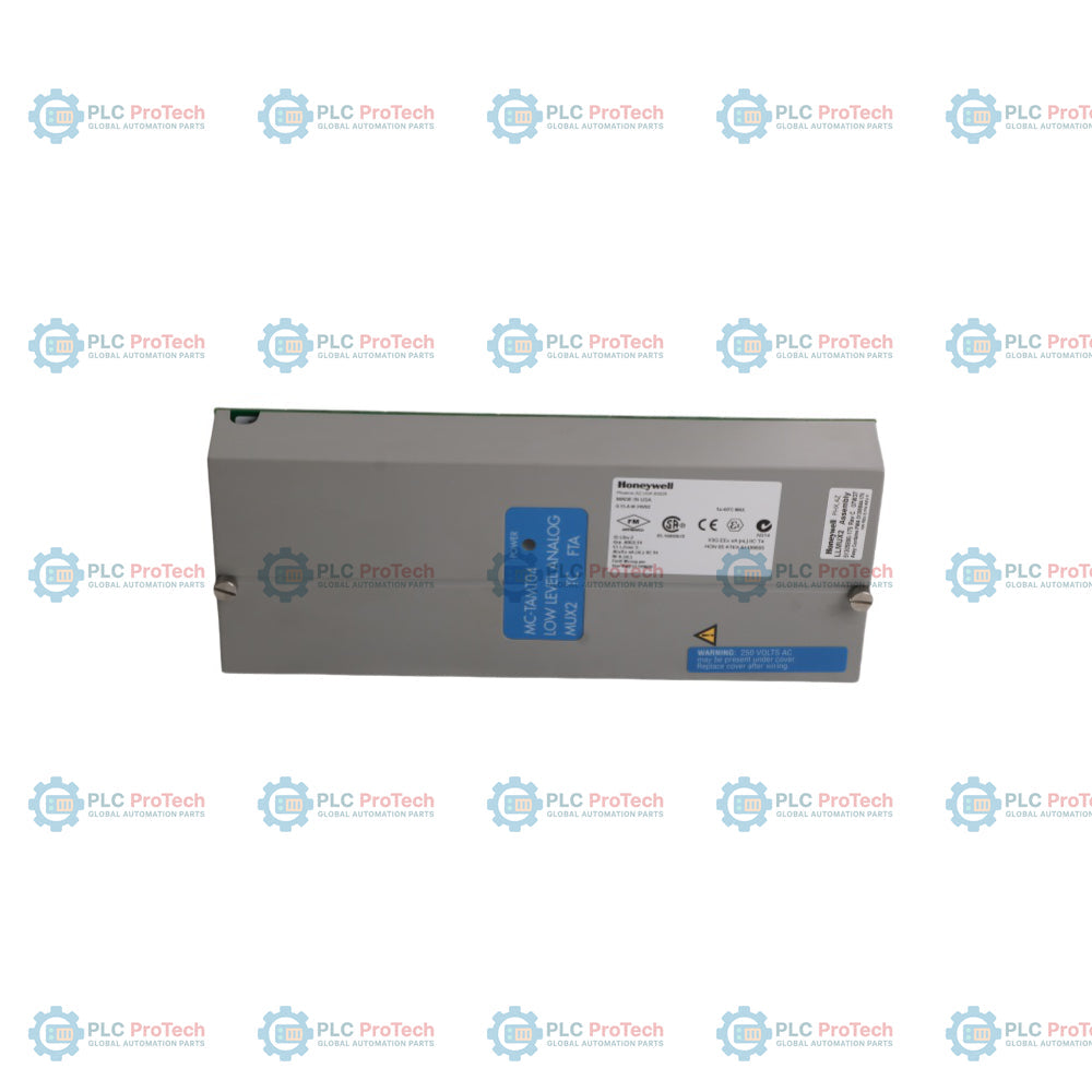
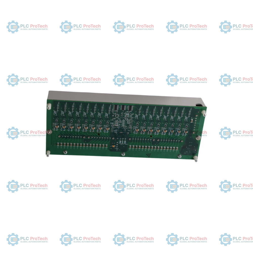
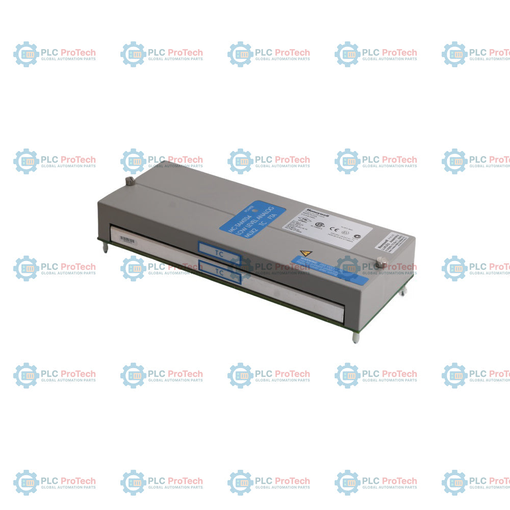
Honeywell MC-TAMT04 (numero di parte 51305890-175) è un gruppo di terminazione di campo per termocoppie LLMUX2 (FTA) a 16 canali e ad alta affidabilità, progettato per l'integrazione con le architetture Honeywell Experion PKS, xPM ed Experion PMIO. Utilizzando l'avanzata tecnologia a stato solido, questo modulo sostituisce i relè tradizionali bagnati al mercurio, eliminando i rischi ambientali e migliorando notevolmente le tolleranze alla resistenza del circuito, consentendo l'uso di cavi per termocoppie di campo più lunghi. Il gruppo è dotato di un riferimento della giunzione fredda (CJR) locale integrato, morsetti a compressione ad alte prestazioni, una singola interfaccia per il processore di ingresso/uscita (IOP) e un robusto rivestimento conforme per il funzionamento continuo in ambienti industriali difficili e corrosivi.
| Parametro | Specifica |
|---|---|
| Produttore | Honeywell |
| Numero di modello | MC-TAMT04 |
| Numero di parte FTA di base | 51305890-175 |
| Canali di ingresso | 16 canali (completamente isolati) |
| Frequenza di scansione dell'ingresso | 1 secondo, fissato da IOLP |
| Larghezza di banda del canale | Da 0 a 4.7 Hz (-3 dB) |
| Intervallo nominale d'ingresso | Da -20 a +100 millivolt |
| Ingresso massimo (senza danni) | Da -10 a +10 volt continui |
| Errore di guadagno | 0.050% del fondo scala massimo (intervallo da -20 a +100 millivolt) |
| Risoluzione della lettura | 2 microvolt per bit |
| Stabilità della temperatura | +/-20 ppm per degC massimo |
| Deriva a lungo termine | 500 ppm |
| Impedenza d'ingresso | 1 megohm in cc |
| Tensione di modo comune (CMV) | +/-250 Vdc o Vac rms (da canale a canale e da canale al comune PM) |
| CMRR (50 o 60 Hz) | 120 dB minimo (con impedenza della sorgente massima di 1000 ohm) |
| NMRR (50 o 60 Hz) | 60 dB minimo |
| Tipi di termocoppia supportati | Tipo J (-200 a +1200 Celsius), Tipo K (-100 a +1370 Celsius), Tipo E (-200 a +1000 Celsius), Tipo T (-230 a +400 Celsius), Tipo B (+100 a +1820 Celsius), Tipo S (0 a +1700 Celsius), Tipo R (0 a +1700 Celsius), Tipo R' giapponese (0 a +1770 Celsius) |
| Intervallo di compensazione della giunzione fredda | Da -20 a +60 degC |
| Precisione della compensazione CJR | +/-0.5 degC tipica |
| Protezione dalle sovratensioni | Certificato IEEE SWC 472-1974 ai terminali del sensore |
| Dissipazione di potenza | 2.25 watt massimo |
| Dissipazione termica | 7.68 Btu all'ora massimo |
| Intervallo della tensione di alimentazione | Da 15 a 30 Vdc (24 Vdc nominali) |
| Corrente di alimentazione | 160 milliampere a 15 Vdc |
| Limiti ambientali di funzionamento | Da 0 a 50 degC; umidità relativa dal 10 al 90% senza condensa (declassamento fino a max 40 degC) |
| Limiti ambientali di stoccaggio | -40 a 80 degC |
| Certificazioni degli enti | Certificato CSA Classe 1, Divisione 2, Gruppi A, B, C, D; certificato UL; conforme CE |
| Dimensioni (A x L x P) | 307.34 mm L x 124.46 mm W x 63.5 mm D (12.1 x 4.9 x 2.5 pollici) |
| Paese di origine | Stati Uniti |
| Peso di spedizione (calcolato) | 1.25 kg (2.75 lbs) |
| Dimensioni della confezione (calcolate) | 360 mm x 180 mm x 100 mm |
MC-TAMT04 è un sostituto diretto, per forma, dimensioni e funzionalità, delle varianti obsolete e non più disponibili di LLMUX TC FTA. Sostituisce senza problemi le schede non conformi CE MU-TAMT02 (51401491-100) e MC-TAMT02 (51401491-150), oltre ai modelli più datati conformi CE MU-TAMT03 (51309223-125) e MC-TAMT03 (51309223-175). In particolare, il gruppo scheda base (51305890-175) è identico a quello utilizzato nel modello di riferimento remoto per la giunzione fredda, MC-TAMT14.
Quando si valutano le resistenze dei loop delle termocoppie di campo, l'architettura a stato solido dell'LLMUX2 offre una capacità di pilotaggio del loop maggiore rispetto ai vecchi sistemi a mercurio, consentendo cavi di campo più lunghi senza perdita di segnale. Tuttavia, gli ingegneri devono gestire attentamente i parametri termici dell'alloggiamento. Il gruppo dissipa continuamente fino a 2,25 watt, generando un carico termico di 7,68 Btu all'ora. Garantire una ventilazione adeguata del pannello se più gruppi sono installati in rack di marshalling ad alta densità, per evitare di superare il limite operativo massimo di 40 degC in ambienti ad alta umidità.
L'unità utilizza un connettore a compressione a 6 pin per il collegamento alla porta J6 situata nella parte superiore del gruppo scheda. Se si aggiorna un vecchio armadio legacy non CE dotato di un connettore a 4 pin, i fili interni devono essere estratti e riadattati nel connettore a 6 pin fornito nel contenitore di spedizione MC-TAMT04. Inoltre, assicurarsi che il ponticello di indirizzo designato come "UNIT" sia impostato correttamente su '0' o '1' per rispecchiare lo schema di indirizzamento del sistema esistente prima di collegare l'interfaccia del cavo J1 a 50 pin al Power Adapter.
Registrare le misure PV di tutti i loop di processo attivi dalla console operativa centrale, per garantire la disponibilità dei parametri di validazione dopo l'installazione.
Scollegare il connettore a nastro principale a 50 pin (J1) dal Power Adapter per disaccoppiare completamente l'LLMUX IOP dal sistema di collegamento locale.
Allentare le viti di ritenzione dei connettori terminali a 8 pin J1, J2, J3 e J4 per farli scorrere lontano dal gruppo senza scollegare i cavi di campo.
Verificare che il ponticello JMP2 sia impostato sulla posizione 'LOC' sulla scheda sostitutiva, per attivare correttamente il circuito del sensore di riferimento della giunzione fredda locale integrato nella scheda.
Montare la scheda nel canale di fissaggio dell'alloggiamento standard, fissare i 4 distanziatori di ritenzione agli angoli, ricollegare i connettori dei terminali e reinstallare la copertura protettiva in plastica.


Global Express Shipping
Returns & Warranty


| Product Image | Model Number / Title | Condition | Availability | Action |
|---|---|---|---|---|

|
Allen-Bradley 1769-IF8 Compact I/O Modulo di ingresso analogico | Original New | In Stock | View Details |
Global Express Shipping
Returns & Warranty
Orders are processed and delivered Monday-Friday (excluding public holidays).
For full eligibility, restocking fees, and international return details, please view our official Refund & Return Policy .
| Color pattern |
Greyish White
Green
|
| Country of origin |
United States
|
| Power source |
DC Power
|

Before moving a TwinCAT 3 license with a Beckhoff C9900-L100, verify the TwinCAT build, XML device description, exact order code and cabinet limits.

A field checklist for replacing a Beckhoff EL4032, covering the ±10 V load, terminal map, power contacts, EtherCAT state, and watchdog behavior.

Before replacing a Yokogawa AAI835, verify the 4-in/4-out channel map, power-loss loop behavior, barrier type, output load, cable, and redundancy.

ABB PM891K01 article 3BSE053241R1 is the non-redundant AC 800M processor kit. Use this field checklist before replacement.

Replacement checks for ABB TP853 3BSE018126R1: identify the installed CI853, CI855, CI857, or CI861 interface, record wiring, and verify communication after installation.

Engineering checks for the Allen-Bradley 5069-L330ERMS2: controller capacity, separate RTB kits, local I/O limits, network-node limits, and motion-axis count.