


Tutto sui PLC: la CPU
A practical engineering guide to PLC CPU operation, from deterministic scan cycles and I/O image tables to memory, communications, diagnostics, redundancy, processor sizing, and reliable system...

Engineered to deliver high-performance motor speed control in heavy industrial configurations, the Mitsubishi Electric FR-E720-5.5K is a three-phase 200V class variable frequency drive from the esteemed FR-E700 Series. Built to handle standard and heavy-duty torque demands, this 5.5 kW (7.5 HP) inverter integrates advanced magnetic flux vector control to supply reliable low-speed torque and dynamic responsiveness. It serves as a dependable control element for machinery requiring rapid acceleration, deceleration, and high-precision velocity regulation.
| Parameter | Specification Value |
|---|---|
| Manufacturer | Mitsubishi Electric |
| Model / Article Number | FR-E720-5.5K |
| Product Series | FR-E700 Series |
| Voltage Class | Three-phase 200V class (200 to 240V AC, 50/60Hz) |
| Inverter Capacity | 5.5 kW (7.5 HP) |
| Recommended MCCB (No Reactor) | 50 A |
| Recommended MCCB (With Reactor) | 40 A |
| Magnetic Contactor (MC) | S-N25 |
| Control Logic Options | Sink (NPN) or Source (PNP) selectable |
| Cooling Method | Forced air cooling (with cooling fan) |
| Net Weight | 4.3 kg |
| Shipping Weight (Calculated) | 7.0 kg |
| Terminal Symbol | Function Description |
|---|---|
| R/L1, S/L2, T/L3 | Main power input terminals (Three-phase 200-240V AC) |
| U, V, W | Inverter output terminals connected directly to the AC induction motor |
| STF / STR | Forward Run / Reverse Run terminal contact command |
| SD | Common terminal for control input contacts (Sink common) |
| PC | Common terminal for transistor outputs and external power source (Source common) |
| 10, 2, 5 | Analog voltage input interface (0 to 10V DC speed reference) |
| 4, 5 | Analog current input interface (4 to 20mA speed reference) |
| A, B, C | Form C relay output contact (Fault/Alarm indicator) |
The FR-E720-5.5K serves as a direct upgrade to legacy FR-E520-5.5K models. Keep in mind that control terminal dimensions and layout differ; the FR-E700 series utilizes a removable control connector card which is not physically compatible with FR-E500 backplanes. Parameter maps are highly consistent, though parameter settings for vector control (Pr. 80 and Pr. 81) must be manually reconfigured to match the motor's slip frequency and excitation current.
During constant torque operation at frequencies below 10 Hz, standard non-ventilated AC motors can overheat rapidly. Under these conditions, specify a force-cooled motor or derate the load. Ensure the continuous ambient temperature in enclosed panels does not exceed 50 degC. If installing multiple drives side-by-side inside a single cabinet, the top shielding plates must be removed to guarantee proper airflow convection.
To transition the digital inputs from standard Sink logic (NPN) to Source logic (PNP), isolate the main power and toggle the physical logic selector switch located directly beneath the control circuit terminal block. When commissioning through terminal 4 (4-20mA current input), set parameter AU (Pr. 184) to activate Terminal 4 input. Run twisted, shielded-pair (STP) wiring for all analog reference cables and ground the shield only at the drive end (Terminal 5) to isolate signal lines from high-frequency common-mode noise.
CRITICAL SAFETY WARNING
Before installing or servicing this drive, fully isolate the mains input power. Wait at least 10 minutes for the internal DC bus capacitors to discharge. Verify the DC bus voltage across terminals P/+ and N/- is below 30V DC using a certified digital multimeter. Failure to follow discharge protocols can result in severe electrical shock, personal injury, or equipment destruction.
Global Express Shipping
Returns & Warranty


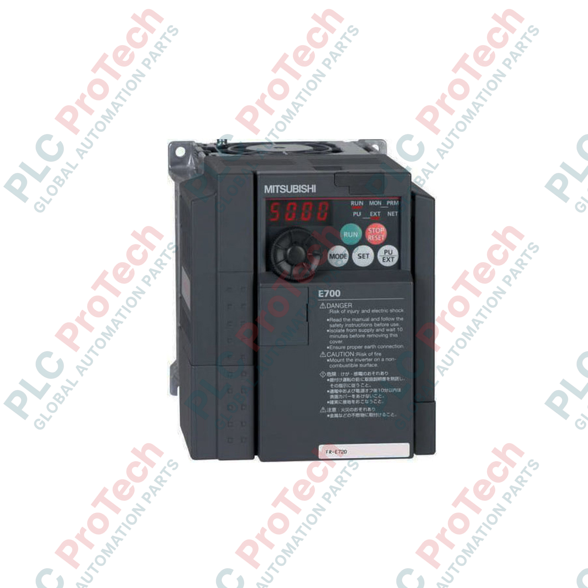
Manufacturer: Mitsubishi Electric
Product No.: FR-E720-5.5K
Country of origin:United States
Product Type: Variable Frequency Drives
Payment: T/T, Western Union
Weight: 500g
Shipping port: Xiamen
Warranty: 12 months
Engineered to deliver high-performance motor speed control in heavy industrial configurations, the Mitsubishi Electric FR-E720-5.5K is a three-phase 200V class variable frequency drive from the esteemed FR-E700 Series. Built to handle standard and heavy-duty torque demands, this 5.5 kW (7.5 HP) inverter integrates advanced magnetic flux vector control to supply reliable low-speed torque and dynamic responsiveness. It serves as a dependable control element for machinery requiring rapid acceleration, deceleration, and high-precision velocity regulation.
| Parameter | Specification Value |
|---|---|
| Manufacturer | Mitsubishi Electric |
| Model / Article Number | FR-E720-5.5K |
| Product Series | FR-E700 Series |
| Voltage Class | Three-phase 200V class (200 to 240V AC, 50/60Hz) |
| Inverter Capacity | 5.5 kW (7.5 HP) |
| Recommended MCCB (No Reactor) | 50 A |
| Recommended MCCB (With Reactor) | 40 A |
| Magnetic Contactor (MC) | S-N25 |
| Control Logic Options | Sink (NPN) or Source (PNP) selectable |
| Cooling Method | Forced air cooling (with cooling fan) |
| Net Weight | 4.3 kg |
| Shipping Weight (Calculated) | 7.0 kg |
| Terminal Symbol | Function Description |
|---|---|
| R/L1, S/L2, T/L3 | Main power input terminals (Three-phase 200-240V AC) |
| U, V, W | Inverter output terminals connected directly to the AC induction motor |
| STF / STR | Forward Run / Reverse Run terminal contact command |
| SD | Common terminal for control input contacts (Sink common) |
| PC | Common terminal for transistor outputs and external power source (Source common) |
| 10, 2, 5 | Analog voltage input interface (0 to 10V DC speed reference) |
| 4, 5 | Analog current input interface (4 to 20mA speed reference) |
| A, B, C | Form C relay output contact (Fault/Alarm indicator) |
The FR-E720-5.5K serves as a direct upgrade to legacy FR-E520-5.5K models. Keep in mind that control terminal dimensions and layout differ; the FR-E700 series utilizes a removable control connector card which is not physically compatible with FR-E500 backplanes. Parameter maps are highly consistent, though parameter settings for vector control (Pr. 80 and Pr. 81) must be manually reconfigured to match the motor's slip frequency and excitation current.
During constant torque operation at frequencies below 10 Hz, standard non-ventilated AC motors can overheat rapidly. Under these conditions, specify a force-cooled motor or derate the load. Ensure the continuous ambient temperature in enclosed panels does not exceed 50 degC. If installing multiple drives side-by-side inside a single cabinet, the top shielding plates must be removed to guarantee proper airflow convection.
To transition the digital inputs from standard Sink logic (NPN) to Source logic (PNP), isolate the main power and toggle the physical logic selector switch located directly beneath the control circuit terminal block. When commissioning through terminal 4 (4-20mA current input), set parameter AU (Pr. 184) to activate Terminal 4 input. Run twisted, shielded-pair (STP) wiring for all analog reference cables and ground the shield only at the drive end (Terminal 5) to isolate signal lines from high-frequency common-mode noise.
CRITICAL SAFETY WARNING
Before installing or servicing this drive, fully isolate the mains input power. Wait at least 10 minutes for the internal DC bus capacitors to discharge. Verify the DC bus voltage across terminals P/+ and N/- is below 30V DC using a certified digital multimeter. Failure to follow discharge protocols can result in severe electrical shock, personal injury, or equipment destruction.
Global Express Shipping
Returns & Warranty
Orders are processed and delivered Monday-Friday (excluding public holidays).
For full eligibility, restocking fees, and international return details, please view our official Refund & Return Policy .
| Country of origin |
United States
|

A practical engineering guide to PLC CPU operation, from deterministic scan cycles and I/O image tables to memory, communications, diagnostics, redundancy, processor sizing, and reliable system...

Sostituire un 1756-L73 non significa automaticamente aggiornare il firmware. Questa guida confronta le versioni 19.013, 21.011 e 31.011, concentrandosi sulla compatibilità dei progetti, sulle...

Implementa un circuito luminoso XOR con 3 interruttori SPST in LogixPro o RSLogix 500 utilizzando un bit di relè interno. Include tabelle della verità, equazioni booleane e verifica.

Integra Allen-Bradley CompactLogix, Caterpillar ATS e generatori nel DCS DeltaV tramite Modbus RTU. Include i gateway ProSoft MVI69-MCM e Miille DIN266.

L’istruzione ONS si attiva, ma la bobina OTE non rimane mai eccitata in Studio 5000 perché il one-shot è vero solo per una scansione. Usa OTL/OTU oppure una logica di autoritenuta.

Configura i servoazionamenti Allen-Bradley Kinetix 5500 su EtherNet/IP. Include CIP Sync, la temporizzazione IEEE 1588 V2, la selezione degli switch Stratix, la topologia DLR e l’HMI.