Mitsubishi Electric

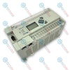
Mitsubishi Electric FX3GE-24MT/ES MELSEC FX3GE Series Programmable Logic Controller

SKU FX3GE-24MT/ES

Disponibile
  • 12-month warranty
  • Free returns within 30 days
  • Manufacturer: Mitsubishi Electric
  • Product No.: FX3GE-24MT/ES
  • Origin United States
  • Product Type: Programmable Logic Controllers
  • Payment: T/T, Western Union
  • Weight: 0.6 kg
  • Dimensions: 8.6 cm x 13 cm x 9 cm
  • Shipping port: Xiamen
  • Warranty: 12 months

Tags

Quantità

Product Description

Description

Serving as a highly integrated hub for compact machine automation, the Mitsubishi Electric FX3GE-24MT/ES is a main unit controller within the MELSEC FX3GE Series. This unit combines the processing capability of the FX3G architecture with embedded Ethernet and analog processing functions in a single, space-saving footprint. It features 14 digital inputs and 10 transistor (sink) outputs alongside built-in analog current/voltage interfaces, eliminating the need for separate expansion adapters for standard networking and analog control tasks.

Key Features

  • Integrated Networking: Embedded RJ45 Ethernet port supporting MC Protocol and CC-Link IE Field Network Basic.
  • Built-In Analog I/O: Includes 2 channels of analog input and 1 channel of analog output (selectable 0-10V DC or 4-20mA).
  • High-Speed Processing: Program execution speeds of 0.21 microseconds per basic instruction.
  • Flexible Expansion: Dual bus architecture allows connection of FX3 series expansion boards and special function blocks.
  • Dual-Polarity Inputs: Digital inputs configurable for either sink or source wiring layouts.

Applications

  • Packaging Machinery: Precise timing and synchronization via high-speed counter inputs.
  • Pumping & Water Treatment: Integrated analog channels manage level, flow, and pressure transmitters directly.
  • Distributed Control Stations: Built-in Ethernet makes this unit an ideal node for distributed factory-floor networks.
  • Material Handling: Local conveyor and sorting control integrated with main system SCADA architectures.

Technical Specifications

Parameter Specification Value
Manufacturer Mitsubishi Electric
Model Reference FX3GE-24MT/ES
Control Series MELSEC FX3GE
Supply Voltage 100 to 240 V AC (+10% / -15%), 50/60 Hz
Power Consumption 32 W
Integrated Digital Inputs 14 points (24 V DC, Sink/Source, 7 mA)
Integrated Digital Outputs 10 points (Transistor, Sink)
Output Capacity 0.5 A per point, 0.8 A per common (Y0-Y3), 1.6 A per common (Y4-Y11)
Integrated Analog Inputs 2 channels (0 to 10 V DC / 4 to 20 mA), 12-bit resolution
Integrated Analog Output 1 channel (0 to 10 V DC / 4 to 20 mA), 12-bit resolution
Communication Ports 1x RJ45 (Ethernet), 1x Mini-USB, 1x RS-422
Operating Temperature 0 to 55 degC (ambient storage: -25 to 75 degC)
Net Weight 0.6 kg
Shipping Weight (Calculated) 2.0 kg
Physical Dimensions 130 mm (W) x 90 mm (H) x 86 mm (D)

Connections and Interfaces

Terminal Code Functional Assignment
L / N 100-240 V AC Power Input Lines
S/S Digital Input Common Terminal (Sink or Source reference)
X000 to X015 24 V DC Digital Inputs (X000-X007 support high-speed counters up to 60 kHz)
COM1 to COM3 Common Terminals for Transistor Outputs
Y000 to Y011 Transistor Outputs (Y000-Y002 support high-speed pulse trains up to 100 kHz)
V1+, V2+, I1+, I2+, COM Analog Inputs (Voltage/Current selectable) & Common Analog ground
V3+, I3+ Analog Output Terminals (Voltage/Current selectable)

Empirical Engineering Insights

Alternative Models & Compatibility

When migration from standard FX3G series processors is required, the FX3GE-24MT/ES is a direct upgrade path. It offers identical terminal footprint dimensions for the core I/O while adding the native Ethernet capability without using expansion slot resources. Note that programming configurations require GX Works2 version 1.090U or later to natively access the integrated Ethernet parameters and built-in analog settings.

Application Pitfalls & Engineering Notes

Because this model utilizes transistor (sink) outputs, inductive loads such as DC solenoid valves or relays must be protected with external flyback diodes wired in parallel with the load. Exceeding the total common-terminal current limit (1.6 A for Y4-Y11) will trigger thermal breakdown of the internal output transistors, which are not user-serviceable.

Commissioning & Wiring Tips

To ensure stable analog measurement, prevent route mixing of the analog signal wires with the AC power supply lines or high-voltage lines. Always use twisted-shielded cables for the 2-channel analog inputs and 1-channel output, grounding the shield at a single point near the PLC chassis ground terminal.

Installation Guidelines

CRITICAL WARNING: Ensure all primary and auxiliary power supplies are completely de-energized before mounting, wiring, or removing terminal blocks. Failure to isolate the power source can result in electrical shock, CPU memory corruption, or permanent damage to the semiconductor junctions of the transistor outputs.
1
Mount the controller onto a standard 35 mm DIN rail (DIN46277). Secure using the integrated DIN rail mounting hooks on the rear. Ensure vertical orientation inside an IP20 or higher enclosure.
2
Connect the main 100-240 V AC power lines to the L and N terminal screws. Ensure a dedicated Class D ground wire (100 ohms or less resistance) is linked directly to the functional ground terminal.
3
Wire the discrete inputs using the S/S terminal to determine Sink or Source mode. Use 24V DC wet contacts for input signals, routing inputs through a separate conduit from high-voltage motor feeds.
4
Configure the IP address parameters via GX Works2 prior to connecting to the production switch, verifying the network subnet masks match your regional field architecture.
Shipping & Returns

Global Express Shipping

  • Standard Delivery: 4–6 business days via DHL, FedEx, and UPS.
  • Express Dispatch: Same-day dispatch for in-stock orders placed before 2:00 PM (GMT+8).
  • Worldwide Coverage: Serving over 150 countries.

Returns & Warranty

  • 30-Day Guarantee: Returns accepted for in-stock products in original, factory-sealed packaging.
  • 12-Month Warranty: Every industrial component is backed by our technical warranty.
FAQ
What is the key difference between the FX3G and FX3GE models?
The FX3GE series includes built-in Ethernet communications and integrated analog inputs (2 channels) and analog output (1 channel) directly on the main CPU block, whereas the standard FX3G requires separate expansion adapters.
Can the digital inputs on the FX3GE-24MT/ES be configured as source inputs?
Yes, the digital inputs feature a flexible S/S (Sink/Source) terminal. Connecting this terminal to 24V DC configures the inputs for Sink logic, while connecting it to 0V DC configures them for Source logic.
What programming software is required for this CPU?
This PLC requires Mitsubishi GX Works2 (version 1.090U or later) or GX Developer to handle the built-in Ethernet and analog interfaces.
What are the limitations of the transistor outputs on this controller?
The outputs are NPN (Sink) transistor types rated at 0.5A per point. They must only switch DC loads (typically 5 to 30V DC). Inductive DC loads require an external clamping diode to protect the internal transistors.
Reviews

FX3GE-24MT/ES

Stock & lead time on request

Call
1 su 1

Mitsubishi Electric FX3GE-24MT/ES MELSEC FX3GE Series Programmable Logic Controller

Only 10 item(s) left in stock
  • Manufacturer: Mitsubishi Electric

  • Product No.: FX3GE-24MT/ES

  • Country of origin:United States

  • Product Type: Programmable Logic Controllers

  • Payment: T/T, Western Union

  • Weight: 600g

  • Dimensions: 8.6 cm x 13 cm x 9 cm

  • Shipping port: Xiamen

  • Warranty: 12 months

Quantità
Visualizza dettagli completi

Product Description

Description

Serving as a highly integrated hub for compact machine automation, the Mitsubishi Electric FX3GE-24MT/ES is a main unit controller within the MELSEC FX3GE Series. This unit combines the processing capability of the FX3G architecture with embedded Ethernet and analog processing functions in a single, space-saving footprint. It features 14 digital inputs and 10 transistor (sink) outputs alongside built-in analog current/voltage interfaces, eliminating the need for separate expansion adapters for standard networking and analog control tasks.

Key Features

  • Integrated Networking: Embedded RJ45 Ethernet port supporting MC Protocol and CC-Link IE Field Network Basic.
  • Built-In Analog I/O: Includes 2 channels of analog input and 1 channel of analog output (selectable 0-10V DC or 4-20mA).
  • High-Speed Processing: Program execution speeds of 0.21 microseconds per basic instruction.
  • Flexible Expansion: Dual bus architecture allows connection of FX3 series expansion boards and special function blocks.
  • Dual-Polarity Inputs: Digital inputs configurable for either sink or source wiring layouts.

Applications

  • Packaging Machinery: Precise timing and synchronization via high-speed counter inputs.
  • Pumping & Water Treatment: Integrated analog channels manage level, flow, and pressure transmitters directly.
  • Distributed Control Stations: Built-in Ethernet makes this unit an ideal node for distributed factory-floor networks.
  • Material Handling: Local conveyor and sorting control integrated with main system SCADA architectures.

Technical Specifications

Parameter Specification Value
Manufacturer Mitsubishi Electric
Model Reference FX3GE-24MT/ES
Control Series MELSEC FX3GE
Supply Voltage 100 to 240 V AC (+10% / -15%), 50/60 Hz
Power Consumption 32 W
Integrated Digital Inputs 14 points (24 V DC, Sink/Source, 7 mA)
Integrated Digital Outputs 10 points (Transistor, Sink)
Output Capacity 0.5 A per point, 0.8 A per common (Y0-Y3), 1.6 A per common (Y4-Y11)
Integrated Analog Inputs 2 channels (0 to 10 V DC / 4 to 20 mA), 12-bit resolution
Integrated Analog Output 1 channel (0 to 10 V DC / 4 to 20 mA), 12-bit resolution
Communication Ports 1x RJ45 (Ethernet), 1x Mini-USB, 1x RS-422
Operating Temperature 0 to 55 degC (ambient storage: -25 to 75 degC)
Net Weight 0.6 kg
Shipping Weight (Calculated) 2.0 kg
Physical Dimensions 130 mm (W) x 90 mm (H) x 86 mm (D)

Connections and Interfaces

Terminal Code Functional Assignment
L / N 100-240 V AC Power Input Lines
S/S Digital Input Common Terminal (Sink or Source reference)
X000 to X015 24 V DC Digital Inputs (X000-X007 support high-speed counters up to 60 kHz)
COM1 to COM3 Common Terminals for Transistor Outputs
Y000 to Y011 Transistor Outputs (Y000-Y002 support high-speed pulse trains up to 100 kHz)
V1+, V2+, I1+, I2+, COM Analog Inputs (Voltage/Current selectable) & Common Analog ground
V3+, I3+ Analog Output Terminals (Voltage/Current selectable)

Empirical Engineering Insights

Alternative Models & Compatibility

When migration from standard FX3G series processors is required, the FX3GE-24MT/ES is a direct upgrade path. It offers identical terminal footprint dimensions for the core I/O while adding the native Ethernet capability without using expansion slot resources. Note that programming configurations require GX Works2 version 1.090U or later to natively access the integrated Ethernet parameters and built-in analog settings.

Application Pitfalls & Engineering Notes

Because this model utilizes transistor (sink) outputs, inductive loads such as DC solenoid valves or relays must be protected with external flyback diodes wired in parallel with the load. Exceeding the total common-terminal current limit (1.6 A for Y4-Y11) will trigger thermal breakdown of the internal output transistors, which are not user-serviceable.

Commissioning & Wiring Tips

To ensure stable analog measurement, prevent route mixing of the analog signal wires with the AC power supply lines or high-voltage lines. Always use twisted-shielded cables for the 2-channel analog inputs and 1-channel output, grounding the shield at a single point near the PLC chassis ground terminal.

Installation Guidelines

CRITICAL WARNING: Ensure all primary and auxiliary power supplies are completely de-energized before mounting, wiring, or removing terminal blocks. Failure to isolate the power source can result in electrical shock, CPU memory corruption, or permanent damage to the semiconductor junctions of the transistor outputs.
1
Mount the controller onto a standard 35 mm DIN rail (DIN46277). Secure using the integrated DIN rail mounting hooks on the rear. Ensure vertical orientation inside an IP20 or higher enclosure.
2
Connect the main 100-240 V AC power lines to the L and N terminal screws. Ensure a dedicated Class D ground wire (100 ohms or less resistance) is linked directly to the functional ground terminal.
3
Wire the discrete inputs using the S/S terminal to determine Sink or Source mode. Use 24V DC wet contacts for input signals, routing inputs through a separate conduit from high-voltage motor feeds.
4
Configure the IP address parameters via GX Works2 prior to connecting to the production switch, verifying the network subnet masks match your regional field architecture.

What is the key difference between the FX3G and FX3GE models?

The FX3GE series includes built-in Ethernet communications and integrated analog inputs (2 channels) and analog output (1 channel) directly on the main CPU block, whereas the standard FX3G requires separate expansion adapters.

Can the digital inputs on the FX3GE-24MT/ES be configured as source inputs?

Yes, the digital inputs feature a flexible S/S (Sink/Source) terminal. Connecting this terminal to 24V DC configures the inputs for Sink logic, while connecting it to 0V DC configures them for Source logic.

What programming software is required for this CPU?

This PLC requires Mitsubishi GX Works2 (version 1.090U or later) or GX Developer to handle the built-in Ethernet and analog interfaces.

What are the limitations of the transistor outputs on this controller?

The outputs are NPN (Sink) transistor types rated at 0.5A per point. They must only switch DC loads (typically 5 to 30V DC). Inductive DC loads require an external clamping diode to protect the internal transistors.

Global Express Shipping

  • Standard Delivery: 4-6 Business Days via DHL, FedEx, and UPS.
  • Express Dispatch: Same-day dispatch for in-stock orders placed before 2:00 PM (GMT+8).
  • Worldwide Coverage: Serving over 150 countries, including rapid delivery to Saudi Arabia and UAE.

Returns & Warranty

  • 30-Day Guarantee: Returns accepted for in-stock products in original, factory-sealed packaging.
  • 12-Month Warranty: Every industrial component is backed by our professional technical warranty.

Orders are processed and delivered Monday-Friday (excluding public holidays).


For full eligibility, restocking fees, and international return details, please view our official Refund & Return Policy .

TECHNICAL SPECIFICATIONS

Country of origin
United States

Technical knowledge

1756-L73 Firmware Upgrade Guide: v19 vs v21/v31 Decision

Replacing a 1756-L73 does not automatically mean upgrading its firmware. This guide compares v19.013, v21.011 and v31.011, focusing on project compatibility, HMI communications, legacy networks and...

Implementing 3-Switch XOR Ladder Logic with Internal Bit

Implement a 3-SPST switch XOR light circuit in LogixPro or RSLogix 500 using an internal relay bit. Includes truth tables, boolean equations, and verified.

Building a Modbus RTU Network with CompactLogix and DeltaV

Integrate Allen-Bradley CompactLogix, Caterpillar ATS, and generators into DeltaV DCS over Modbus RTU. Covers ProSoft MVI69-MCM, Miille DIN266 gateways.

ONS Instruction Not Energizing OTE in Studio 5000 Ladder Logic

ONS instruction fires but the OTE coil never latches in Studio 5000 because the one-shot is only true for one scan. Use OTL/OTU or seal-in logic instead.

Kinetix 5500 EtherNet/IP Network Switch Requirements and Topology

Configure Allen-Bradley Kinetix 5500 servo drives on EtherNet/IP. Covers CIP Sync, IEEE 1588 V2 timing, Stratix selection, DLR topology, and HMI.

Moving Average Filtering in DCS and PLC Analog Control

A moving-average filter is the sliding-window smoother most instrument engineers drop into DCS and PLC analog paths. Here is how the window works, how N and sample time set lag, and when a...