Omron

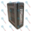
Omron CJ1W-AD041-V1 CJ Series Analog Input Unit

SKU ÿCJ1W-AD041-V1

Disponibile
  • 12-month warranty
  • Free returns within 30 days
  • Manufacturer: Omron
  • Product No.: ÿCJ1W-AD041-V1
  • Origin Japan
  • Product Type: Analog Output Modules
  • Payment: T/T, Western Union
  • Weight: 1.5 kg
  • Dimensions: 125 x 105 x 35 mm
  • Shipping port: Xiamen
  • Warranty: 12 months

Tags

Quantità

Product Description

Description

Integrating seamlessly into Omron Sysmac CJ-series PLCs, the Omron CJ1W-AD041-V1 provides high-density, precise analog-to-digital conversion across four physical input channels. This module processes voltage and current field transmitter signals, translating physical variables into highly accurate digital data blocks. Its backplane-driven processor supports advanced signal scaling, peak-hold execution, and customized input filtration algorithms directly inside the memory allocation table, eliminating the need for complex ladder-logic averaging routines.

Features

  • Four Selectable Channels: Individual configuration per channel for current (4 to 20 mA) or voltage (1 to 5 V, 0 to 5 V, 0 to 10 V, -10 to +10 V) inputs.
  • High-Speed A/D Conversion: Configurable conversion speeds reaching up to 250 microseconds per point in high-speed mode.
  • Selectable Resolution Modes: Offers standard 1/4000 resolution or high-resolution 1/8000 mode for ultra-precise process variable tracking.
  • Detachable Terminal Block: Features an 18-point detachable M3 screw terminal block, enabling swift module replacements without re-wiring.
  • Built-In Diagnostics: Real-time detection of input wire disconnection, over-range levels, and internal hardware faults.

Applications

  • Chemical processing and multi-loop temperature tracking via 4-20 mA transmitters.
  • Water and wastewater monitoring involving volumetric flow and pressure transmitters.
  • Variable frequency drive (VFD) speed-feedback control systems.
  • Precise packaging and tension-control systems utilizing load cells and signal conditioners.

Technical Specifications

Parameter Specification Values
Manufacturer Omron Industrial Automation
Model Number CJ1W-AD041-V1
Product Series CJ Series (CJ1G, CJ1H, CJ1M, CJ2M, CJ2H)
Number of Analog Inputs 4 Channels
Input Voltage Ranges 0 to 5 V, 1 to 5 V, 0 to 10 V, -10 to +10 V
Input Current Ranges 4 to 20 mA
Resolution Options 1/4000 (Standard), 1/8000 (High-Resolution Mode)
Conversion Time 1.0 ms/point max. (Standard), 250 microsec/point max. (High-Speed)
Accuracy (25 degC) Voltage: +/-0.2% of FS; Current: +/-0.4% of FS
Channel-to-Channel Isolation None (Common ground plane)
Backplane Bus Isolation Photocoupler isolated between input terminals and CPU internal logic
Internal Current Consumption 0.42 A at 5 VDC (Backplane rail)
External Wiring Terminal 18-point detachable terminal block (M3 screws)
Standards & Approvals CE, UL (Class I Div 2), NK, Lloyd's
Country of Origin Japan
Shipping Weight (Calculated) 0.32 kg
Package Dimensions (Calculated) 125 x 105 x 35 mm

Connections and Interfaces

Terminal No. Signal Label Description
1 V IN 1 Voltage Input Terminal, Channel 1
2 I IN 1 Current Input Terminal, Channel 1
3 COM 1 Common Terminal, Channel 1
4 V IN 2 Voltage Input Terminal, Channel 2
5 I IN 2 Current Input Terminal, Channel 2
6 COM 2 Common Terminal, Channel 2
7 V IN 3 Voltage Input Terminal, Channel 3
8 I IN 3 Current Input Terminal, Channel 3
9 COM 3 Common Terminal, Channel 3
10 V IN 4 Voltage Input Terminal, Channel 4
11 I IN 4 Current Input Terminal, Channel 4
12 COM 4 Common Terminal, Channel 4
13 to 17 NC No Connection (Do not wire)
18 SLD Shield Terminal (Internal system ground)

Empirical Engineering Insights

Alternative Models & Compatibility

The "V1" suffix indicates critical updates over the legacy non-V1 module. It introduces the high-resolution mode (1/8000 conversion) and reduces overall conversion times down to 250 microseconds per channel. The module is fully backward compatible; however, if you are upgrading from an older version in a system that utilized specific unit settings, you must reconfirm the I/O allocation mapping in CX-Programmer to ensure the CPU can register the newer features.

Application Pitfalls & Engineering Notes

This unit features non-isolated input channels, meaning all four channels share a common internal ground plane. If you feed analog signals from devices powered by different external DC supplies, ground-loop offset voltages will distort the analog readings or potentially trigger hardware faults on the module. For isolated channels, choose the CJ1W-AD042 or add signal isolators externally on each loop.

Commissioning & Wiring Tips

Always route the analog signal cabling away from high-voltage motor power cables to mitigate EMI noise coupling. Connect the shield line of the twisted-pair cable exclusively to the SLD terminal (Pin 18) on the module's terminal block. Unused channels must be explicitly disabled in the software configuration; otherwise, they will float and cause the PLC's internal error flags to cycle unexpectedly.

Installation Guidelines

CRITICAL WARNING

Do not insert or remove the CJ1W-AD041-V1 module from the PLC backplane while the rack is powered. De-energize the main control supply completely and allow all internal bus charges to bleed down to zero before handling. Live insertion will damage the backplane interface ASIC and corrupt the memory tables within the CPU module.

1
Align the structural hook on the upper section of the module with the slot on the PLC backplane. Rotate the module downwards until it seats flush.
2
Secure the unit by locking the yellow slider mechanisms at both the top and bottom of the module casing. Ensure they click completely into place.
3
Wire current loops using the I IN and COM terminals; wire voltage loops via the V IN and COM terminals. Tighten terminal block screws to a maximum torque of 0.5 N-m.
Shipping & Returns

Global Express Shipping

  • Standard Delivery: 4–6 business days via DHL, FedEx, and UPS.
  • Express Dispatch: Same-day dispatch for in-stock orders placed before 2:00 PM (GMT+8).
  • Worldwide Coverage: Serving over 150 countries.

Returns & Warranty

  • 30-Day Guarantee: Returns accepted for in-stock products in original, factory-sealed packaging.
  • 12-Month Warranty: Every industrial component is backed by our technical warranty.
FAQ
Can I mix voltage and current signals on the same CJ1W-AD041-V1 module?
Yes. Each of the four channels can be configured independently for either voltage or current signals in the software settings, using the dedicated terminal assignments for each channel.
What is the consequence of not isolating signals on this card?
Since there is no channel-to-channel isolation, sharing different ground loops across channels can inject ground currents, offset voltages, and noise, potentially skewing signals or damaging input circuitry.
How do I configure the module for high-resolution 1/8000 mode?
Resolution is adjusted by accessing the DM area settings corresponding to the unit's allocated memory words within CX-Programmer, and setting the resolution flag high prior to PLC initialization.
Do I need external shunt resistors to measure current inputs?
No, the card features built-in current measurement circuitry. You wire the current source loop directly to the designated I IN and COM terminals of the respective channel.
Reviews

ÿCJ1W-AD041-V1

Stock & lead time on request

Call
1 su 1

Omron CJ1W-AD041-V1 CJ Series Analog Input Unit

Only 8 item(s) left in stock
  • Manufacturer: Omron

  • Product No.: ÿCJ1W-AD041-V1

  • Country of origin:Japan

  • Product Type: Analog Output Modules

  • Payment: T/T, Western Union

  • Weight: 1500g

  • Dimensions: 125 x 105 x 35 mm

  • Shipping port: Xiamen

  • Warranty: 12 months

Quantità
Visualizza dettagli completi

Product Description

Description

Integrating seamlessly into Omron Sysmac CJ-series PLCs, the Omron CJ1W-AD041-V1 provides high-density, precise analog-to-digital conversion across four physical input channels. This module processes voltage and current field transmitter signals, translating physical variables into highly accurate digital data blocks. Its backplane-driven processor supports advanced signal scaling, peak-hold execution, and customized input filtration algorithms directly inside the memory allocation table, eliminating the need for complex ladder-logic averaging routines.

Features

  • Four Selectable Channels: Individual configuration per channel for current (4 to 20 mA) or voltage (1 to 5 V, 0 to 5 V, 0 to 10 V, -10 to +10 V) inputs.
  • High-Speed A/D Conversion: Configurable conversion speeds reaching up to 250 microseconds per point in high-speed mode.
  • Selectable Resolution Modes: Offers standard 1/4000 resolution or high-resolution 1/8000 mode for ultra-precise process variable tracking.
  • Detachable Terminal Block: Features an 18-point detachable M3 screw terminal block, enabling swift module replacements without re-wiring.
  • Built-In Diagnostics: Real-time detection of input wire disconnection, over-range levels, and internal hardware faults.

Applications

  • Chemical processing and multi-loop temperature tracking via 4-20 mA transmitters.
  • Water and wastewater monitoring involving volumetric flow and pressure transmitters.
  • Variable frequency drive (VFD) speed-feedback control systems.
  • Precise packaging and tension-control systems utilizing load cells and signal conditioners.

Technical Specifications

Parameter Specification Values
Manufacturer Omron Industrial Automation
Model Number CJ1W-AD041-V1
Product Series CJ Series (CJ1G, CJ1H, CJ1M, CJ2M, CJ2H)
Number of Analog Inputs 4 Channels
Input Voltage Ranges 0 to 5 V, 1 to 5 V, 0 to 10 V, -10 to +10 V
Input Current Ranges 4 to 20 mA
Resolution Options 1/4000 (Standard), 1/8000 (High-Resolution Mode)
Conversion Time 1.0 ms/point max. (Standard), 250 microsec/point max. (High-Speed)
Accuracy (25 degC) Voltage: +/-0.2% of FS; Current: +/-0.4% of FS
Channel-to-Channel Isolation None (Common ground plane)
Backplane Bus Isolation Photocoupler isolated between input terminals and CPU internal logic
Internal Current Consumption 0.42 A at 5 VDC (Backplane rail)
External Wiring Terminal 18-point detachable terminal block (M3 screws)
Standards & Approvals CE, UL (Class I Div 2), NK, Lloyd's
Country of Origin Japan
Shipping Weight (Calculated) 0.32 kg
Package Dimensions (Calculated) 125 x 105 x 35 mm

Connections and Interfaces

Terminal No. Signal Label Description
1 V IN 1 Voltage Input Terminal, Channel 1
2 I IN 1 Current Input Terminal, Channel 1
3 COM 1 Common Terminal, Channel 1
4 V IN 2 Voltage Input Terminal, Channel 2
5 I IN 2 Current Input Terminal, Channel 2
6 COM 2 Common Terminal, Channel 2
7 V IN 3 Voltage Input Terminal, Channel 3
8 I IN 3 Current Input Terminal, Channel 3
9 COM 3 Common Terminal, Channel 3
10 V IN 4 Voltage Input Terminal, Channel 4
11 I IN 4 Current Input Terminal, Channel 4
12 COM 4 Common Terminal, Channel 4
13 to 17 NC No Connection (Do not wire)
18 SLD Shield Terminal (Internal system ground)

Empirical Engineering Insights

Alternative Models & Compatibility

The "V1" suffix indicates critical updates over the legacy non-V1 module. It introduces the high-resolution mode (1/8000 conversion) and reduces overall conversion times down to 250 microseconds per channel. The module is fully backward compatible; however, if you are upgrading from an older version in a system that utilized specific unit settings, you must reconfirm the I/O allocation mapping in CX-Programmer to ensure the CPU can register the newer features.

Application Pitfalls & Engineering Notes

This unit features non-isolated input channels, meaning all four channels share a common internal ground plane. If you feed analog signals from devices powered by different external DC supplies, ground-loop offset voltages will distort the analog readings or potentially trigger hardware faults on the module. For isolated channels, choose the CJ1W-AD042 or add signal isolators externally on each loop.

Commissioning & Wiring Tips

Always route the analog signal cabling away from high-voltage motor power cables to mitigate EMI noise coupling. Connect the shield line of the twisted-pair cable exclusively to the SLD terminal (Pin 18) on the module's terminal block. Unused channels must be explicitly disabled in the software configuration; otherwise, they will float and cause the PLC's internal error flags to cycle unexpectedly.

Installation Guidelines

CRITICAL WARNING

Do not insert or remove the CJ1W-AD041-V1 module from the PLC backplane while the rack is powered. De-energize the main control supply completely and allow all internal bus charges to bleed down to zero before handling. Live insertion will damage the backplane interface ASIC and corrupt the memory tables within the CPU module.

1
Align the structural hook on the upper section of the module with the slot on the PLC backplane. Rotate the module downwards until it seats flush.
2
Secure the unit by locking the yellow slider mechanisms at both the top and bottom of the module casing. Ensure they click completely into place.
3
Wire current loops using the I IN and COM terminals; wire voltage loops via the V IN and COM terminals. Tighten terminal block screws to a maximum torque of 0.5 N-m.

Can I mix voltage and current signals on the same CJ1W-AD041-V1 module?

Yes. Each of the four channels can be configured independently for either voltage or current signals in the software settings, using the dedicated terminal assignments for each channel.

What is the consequence of not isolating signals on this card?

Since there is no channel-to-channel isolation, sharing different ground loops across channels can inject ground currents, offset voltages, and noise, potentially skewing signals or damaging input circuitry.

How do I configure the module for high-resolution 1/8000 mode?

Resolution is adjusted by accessing the DM area settings corresponding to the unit's allocated memory words within CX-Programmer, and setting the resolution flag high prior to PLC initialization.

Do I need external shunt resistors to measure current inputs?

No, the card features built-in current measurement circuitry. You wire the current source loop directly to the designated I IN and COM terminals of the respective channel.

Global Express Shipping

  • Standard Delivery: 4-6 Business Days via DHL, FedEx, and UPS.
  • Express Dispatch: Same-day dispatch for in-stock orders placed before 2:00 PM (GMT+8).
  • Worldwide Coverage: Serving over 150 countries, including rapid delivery to Saudi Arabia and UAE.

Returns & Warranty

  • 30-Day Guarantee: Returns accepted for in-stock products in original, factory-sealed packaging.
  • 12-Month Warranty: Every industrial component is backed by our professional technical warranty.

Orders are processed and delivered Monday-Friday (excluding public holidays).


For full eligibility, restocking fees, and international return details, please view our official Refund & Return Policy .

TECHNICAL SPECIFICATIONS

Country of origin
Japan

Technical knowledge

1756-L73 Firmware Upgrade Guide: v19 vs v21/v31 Decision

Replacing a 1756-L73 does not automatically mean upgrading its firmware. This guide compares v19.013, v21.011 and v31.011, focusing on project compatibility, HMI communications, legacy networks and...

Implementing 3-Switch XOR Ladder Logic with Internal Bit

Implement a 3-SPST switch XOR light circuit in LogixPro or RSLogix 500 using an internal relay bit. Includes truth tables, boolean equations, and verified.

Building a Modbus RTU Network with CompactLogix and DeltaV

Integrate Allen-Bradley CompactLogix, Caterpillar ATS, and generators into DeltaV DCS over Modbus RTU. Covers ProSoft MVI69-MCM, Miille DIN266 gateways.

ONS Instruction Not Energizing OTE in Studio 5000 Ladder Logic

ONS instruction fires but the OTE coil never latches in Studio 5000 because the one-shot is only true for one scan. Use OTL/OTU or seal-in logic instead.

Kinetix 5500 EtherNet/IP Network Switch Requirements and Topology

Configure Allen-Bradley Kinetix 5500 servo drives on EtherNet/IP. Covers CIP Sync, IEEE 1588 V2 timing, Stratix selection, DLR topology, and HMI.

Moving Average Filtering in DCS and PLC Analog Control

A moving-average filter is the sliding-window smoother most instrument engineers drop into DCS and PLC analog paths. Here is how the window works, how N and sample time set lag, and when a...