Description
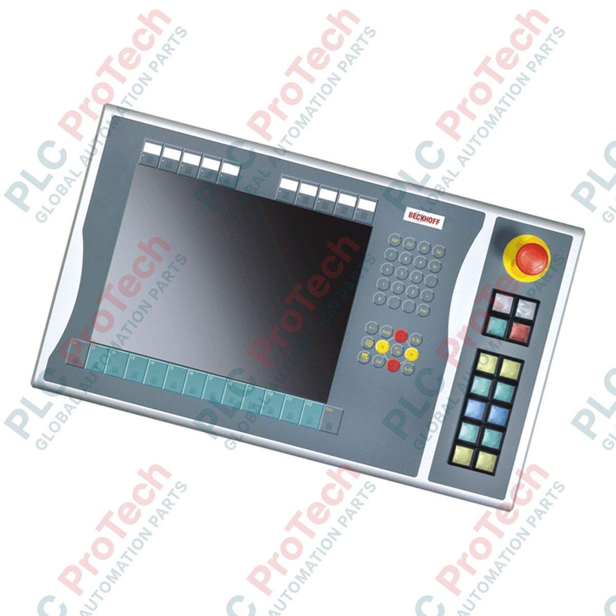
Interfacing directly with 15-inch display configurations, the Beckhoff C9900-E801 delivers external physical control capabilities to CP6xxx and CP7xxx Control Panels and Panel PCs. Designed specifically for display-only panels without integrated physical keyboards, this extension mounts securely to the right-hand side of the host terminal, providing immediate operator access to high-priority machinery operations. It consolidates tactile status indication and functional hardware controls into a rugged industrial housing, reducing front-panel wiring complexity while preserving mechanical integrity in harsh automation environments.
Key Features
- Direct right-side integration with Beckhoff CP6x21-00xx and CP7x21-00xx 15-inch HMI systems.
- Equipped with 12 square Siemens Signum push-buttons (30 x 30 mm) incorporating integrated active feedback lamps.
- Includes 1 dedicated high-visibility Siemens Signum emergency stop button for physical hardware circuit interruption.
- Dual-channel key contact system: First normally-open (NO) contacts map electronically via CP-Link or USB.
- Direct hardwired terminal strip access for secondary NO contacts, enabling physical wiring configurations.
- Removable transparent button caps allow customized on-site labeling and icon identification.
Applications
- Machine tool control panels requiring physical cycle start, hold, and jog overrides.
- Automotive body-shop visualization terminals where hardware safety interlocks must sit adjacent to the HMI screen.
- Process plants requiring non-software-dependent emergency shutdown triggers at operator control points.
Technical Specifications
| Specification Parameter |
Value / Rating |
| Manufacturer |
Beckhoff Automation |
| Part Number |
C9900-E801 |
| Compatible Series |
CP6x21-00xx, CP7x21-00xx (15-inch displays without keyboards) |
| Mounting Location |
Right side of host Control Panel |
| Push-Button Type |
12 x Siemens Signum (30 x 30 mm square, with signal lamp) |
| Emergency Stop Key |
1 x Siemens Signum, direct hardware-wireable |
| Signal Lamp Control |
Transmitted exclusively via CP-Link or USB connection |
| Contact Configuration |
Primary NO contact: CP-Link / USB; Secondary NO contact: Direct wire terminals |
| Labeling System |
Insertable labels under transparent push-button caps |
| Shipping Weight (Calculated) |
5.0 kg (approx. 11.0 lbs) |
Alternative Models & Compatibility
The C9900-E801 is configured specifically for right-side installation on 15-inch non-keyboard panels. Ensure that your host panel is the CP6x21-00xx or CP7x21-00xx configuration. If a different display size (e.g., 12-inch or 19-inch) or alternative button configuration is present in your line layout, contact engineering support to ensure correct dimensional and mounting alignment before physical deployment.
Application Pitfalls & Engineering Notes
Note that the integrated signal lamps operate exclusively over the communication bus (CP-Link or USB). Do not rely on indicator light statuses for safety-critical state feedback if active PC communication is interrupted. In circumstances where communication is severed, only the physical, hardwired secondary contact terminals remain operational.
Commissioning & Wiring Tips
To configure hardwired safety loops, route dedicated two-wire connections from the emergency stop and the secondary push-button terminal blocks back to your local safety evaluation relay or TwinSAFE system. Route digital signal cables and low-voltage command runs separately from motor-drive cables to avoid electrical interference across the communication interface.
Installation Guidelines
CRITICAL WARNING: Isolate all primary and auxiliary power sources from the main Control Panel and adjacent enclosure connections before mechanical or electrical mounting. Confirm zero voltage state via multi-meter verification prior to cable integration.
1
Mount the C9900-E801 chassis directly to the right side of the host 15-inch display unit using the provided alignment brackets.
2
Secure the mechanical connection, ensuring even torque distribution across all mounting elements to preserve physical integrity and IP ratings.
3
Connect the communication interface cable (CP-Link or USB) directly to the corresponding host port on the Panel PC.
4
Wire the emergency stop contact directly to the emergency stop loop, and terminate any second-channel digital contacts to your I/O subsystem.