Description
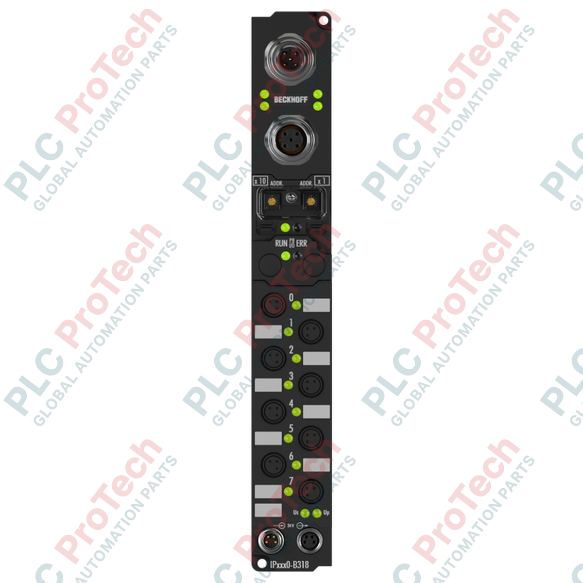
Decentralized automation tasks in harsh environments are directly addressed by the Beckhoff IP2300-B310, an IP67-rated Fieldbus Box designed to bridge field sensors and actuators directly with a PROFIBUS DP network without requiring a protective control cabinet. This space-saving module integrates four digital inputs featuring a fixed 3 ms filter alongside four short-circuit-proof digital outputs rated at 0.5 A per channel. Utilizing robust M8 circular connectors, the device minimizes cabling overhead, isolates network noise, and provides local diagnostic feedback via dedicated status LEDs for seamless diagnostics on the factory floor.
Features
-
Direct Machine Mounting: IP67-rated enclosure permits cabinet-free deployment, lowering thermal loads within main enclosures and optimizing cable runs.
-
Robust Fieldbus Connectivity: Embedded PROFIBUS DP interface supporting transmission speeds up to 12 Mbaud with automatic baud rate detection.
-
Comprehensive Digital I/O: Built with 4 digital inputs (24 V DC, 3 ms filter) and 4 digital outputs (24 V DC, 0.5 A load capacity).
-
Enhanced Circuit Protection: Output stages are short-circuit and overload protected, ensuring resilient field operations during actuator failures.
-
M8 Connector Interface: High-density, screw-lock M8 connections guarantee mechanical stability in high-vibration machinery.
Applications
- Decentralized material handling and heavy conveyor systems.
- Robotic end-of-arm tooling and end-effector sensor consolidation.
- Pneumatic valve terminal control in automotive assembly areas.
- Packaging machinery requiring distributed IP67-rated I/O architectures.
Technical Specifications
| Manufacturer |
Beckhoff |
| Model Reference |
IP2300-B310 |
| Product Series |
Fieldbus Box (IPxxxx Series) |
| Fieldbus Protocol |
PROFIBUS DP (up to 12 Mbaud) |
| Digital Inputs |
4 channels, 24 V DC (nominal) |
| Input Filter Delay |
3.0 ms |
| Digital Outputs |
4 channels, 24 V DC, short-circuit proof |
| Max. Output Current |
0.5 A per channel (2.0 A total module load) |
| Connection Style |
M8 screw-type connectors for digital channels |
| Control Voltage |
24 V DC (-15% / +20%) |
| Current Consumption |
Approx. 40 mA from control voltage + sensor load |
| Protection Class |
IP67 (when all connection ports are sealed) |
| Operating Temperature |
0 degC to +55 degC |
| Storage Temperature |
-25 degC to +85 degC |
| Shipping Weight (Calculated) |
0.35 kg (excluding outer shipping carton) |
| Package Dimensions (Calculated) |
126 mm x 30 mm x 26.5 mm |
Connections and Interfaces
| M8 Port Pin |
Input Function / Assignment |
Output Function / Assignment |
| Pin 1 |
+24 V DC sensor supply (Us) |
Not connected (NC) / Reserve |
| Pin 3 |
0 V Ground (GNDs) |
0 V Ground (GNDp) |
| Pin 4 |
Digital Input Signal (DI1 to DI4) |
Digital Output Signal (DO1 to DO4) |
Alternative Models & Compatibility
This unit serves as a standard Profibus I/O module. When transitioning from older IP2300 hardware revisions, confirm the rotary address switch behavior matches your master configuration. If moving to industrial Ethernet architectures like EtherCAT, direct equivalents are available within the Beckhoff EP2308-0001 EtherCAT Box series, which features a similar I/O density and M8 form factor.
Application Pitfalls & Engineering Notes
When switching highly inductive DC loads (such as heavy pneumatic solenoids or magnetic brakes), flyback currents can degrade the internal output switches over time. While the digital outputs are electronically protected, deploying an external flyback diode directly at the inductive load terminals is recommended to maximize hardware longevity. Additionally, avoid exceeding the maximum group limit of 2.0 A total output current across all active output channels to prevent thermal shutdown of the internal driver IC.
Commissioning & Wiring Tips
The PROFIBUS DP address must be defined manually using the two decimal rotary switches protected beneath the clear threaded cap on the front of the module. To ensure the IP67 seal rating remains valid, verify that the clear cap is tightened to its proper torque specification (0.6 Nm) and that any unused M8 ports are securely sealed using standard IP67-rated protective plugs.
Installation Guidelines
CRITICAL WARNING
Isolate all power sources supplying the host control panel and field equipment before beginning physical mounting or wiring of this fieldbus module. Dangerous electrical shock risks, short-circuits, and unexpected actuator triggering may occur if connections are modified while power is active.
1
Securely mount the fieldbus box to a flat, rigid machine surface using two M4 bolts through the pre-cast mounting holes. Ensure the surface is free from sharp vibration sources.
2
Configure the desired PROFIBUS address (from 1 to 99) via the integrated rotary switches before connecting power or fieldbus cables.
3
Connect the incoming fieldbus cable to the designated PROFIBUS interface and terminate the line if the module sits at the physical end of the bus trunk.
4
Attach the M8 I/O cables, ensuring the locking collars are fully tightened to maintain the IP67 water and dust seal. Cap any unused channels immediately.