Description
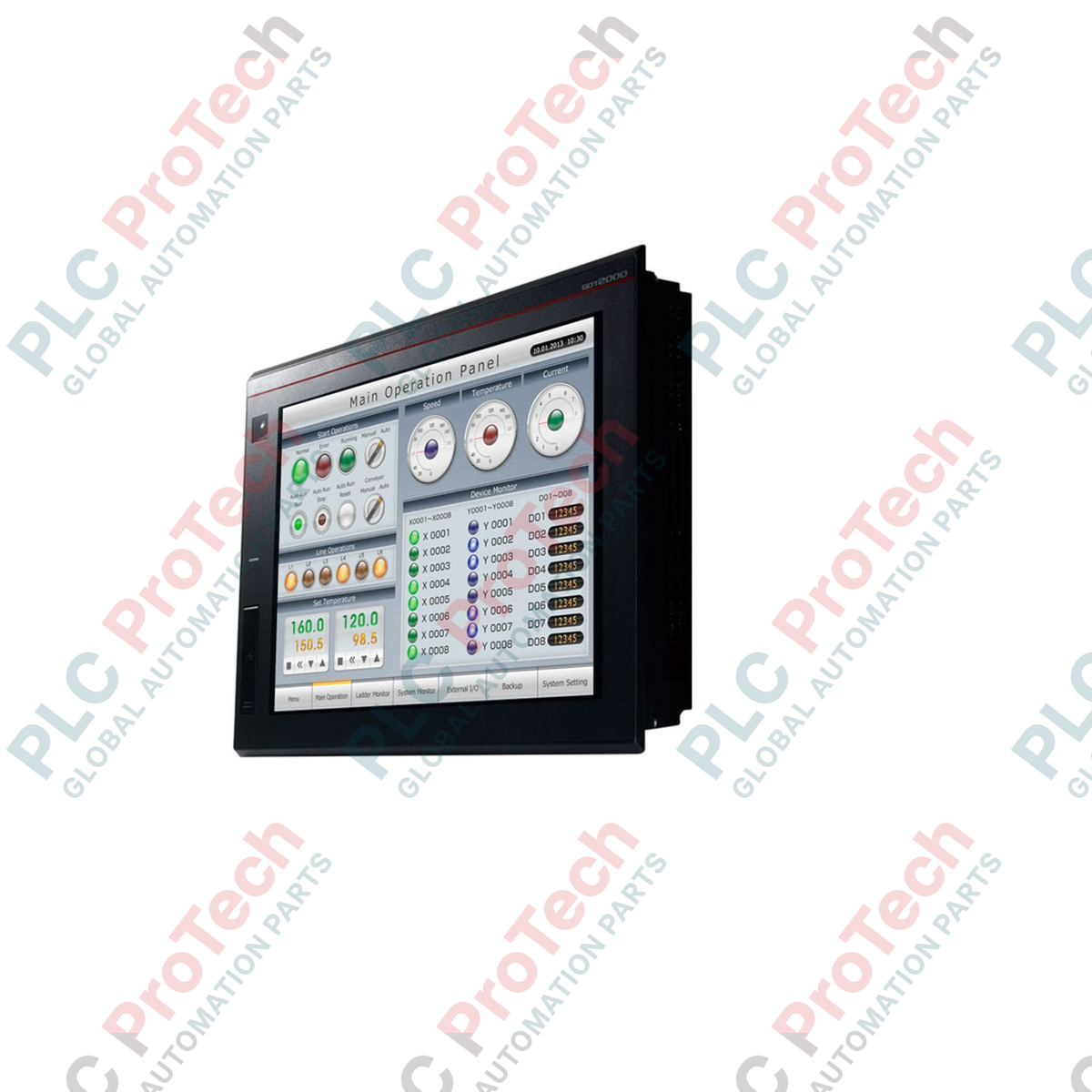
Operating as a central visualization bridge in modern control architectures, the Mitsubishi Electric GT2508-STBD graphic operation terminal delivers reliable performance for machine-level monitoring. This high-performance HMI features an 8.4-inch TFT color display with SVGA resolution (640 x 480 pixels), providing clear system diagnostics and process representation in space-constrained industrial panels. Engineered for integration with MELSEC PLCs and third-party controllers, it incorporates multi-touch capabilities to allow gestures such as pinching, zooming, and scrolling. The unit operates on standard 24 VDC power, features a black bezel, and hosts extensive connectivity interfaces, including Ethernet, serial, and USB ports to handle high-speed data transfers and logging.
Key Features
-
High-Contrast Display: 8.4-inch TFT color LCD screen rendering 65,536 colors at SVGA resolution.
-
Intelligent Multi-Touch: Supports dual-point touch commands for safe, multi-step operation and screen navigation.
-
Flexible Connectivity: Built-in Ethernet, RS-232, and RS-422/485 serial ports for diverse field communication.
-
Storage Expansion: Dedicated SD memory card slot and dual USB ports (Host and Device) for project management and diagnostics logging.
-
Robust Protection: Front panel rating conforms to IP67F standard protection against dust and water ingress when mounted.
Applications
- Automotive assembly line work cells.
- Water treatment processing and localized pumping stations.
- Packaging, sorting, and material handling systems.
- Chemical batching and food production control desks.
Technical Specifications
| Parameter |
Specification |
| Manufacturer |
Mitsubishi Electric |
| Model Identifier |
GT2508-STBD |
| Series |
GOT2000 / GT25 |
| Display Size |
8.4 Inches |
| Display Type |
TFT Color LCD |
| Resolution |
SVGA (640 x 480 pixels) |
| Backlight Unit |
LED (Non-replaceable, long-life) |
| Rated Input Voltage |
24 VDC (+25%, -20%) |
| Frame Color |
Black |
| Memory Capacity |
User Memory: 32 MB |
| Panel Cutout Dimensions |
227 mm x 176 mm |
| Operating Temperature Range |
0 to 55 degC |
| Shipping Weight |
8.0 kg (including secure packaging) |
Connections and Interfaces
| Interface Port |
Function / Connection Assignment |
| Ethernet Port |
1x RJ45, 100BASE-TX/10BASE-T for PLC communication and network configuration |
| RS-232 Port |
1x D-Sub 9-pin (Male) for legacy controller integration or barcode readers |
| RS-422/485 Port |
1x D-Sub 9-pin (Female) for high-speed differential serial networks |
| USB Host Port |
1x USB Type A (USB 2.0) for connecting external mice, keyboards, or storage |
| USB Device Port |
1x USB Mini-B (USB 2.0) for project upload/download via local PC connection |
Empirical Engineering Insights
Alternative Models & Compatibility
The GT2508-STBD serves as a standard form-factor replacement for legacy GOT1000 Series 8.4-inch units. When migrating from older installations, note that while the unit matches standard panel cutout profiles (227 mm x 176 mm), it has a slim-body design requiring less depth clearance inside the cabinet. Project conversion is managed seamlessly through MELSOFT GT Works3 software.
Application Pitfalls & Engineering Notes
When utilizing the logging and data backup functions, ensure that only industrial-grade SD cards are deployed. Standard consumer-grade SD cards face rapid write-cycle exhaustion under continuous parameter logging regimes, which can lead to file system corruption and system lockups. Ensure at least 100 mm of physical clearance at the rear and top of the unit for unrestricted cooling airflow.
Commissioning & Wiring Tips
For reliable performance in high-noise environments, the frame ground (FG) terminal must be wired directly to a dedicated Class D electrical ground with a resistance of 100 ohms or less. Avoid running the 24 VDC power lines in the same wire duct as high-voltage AC motor lines or VFD outputs to prevent electrical noise coupling into the sensitive logic boards.
Installation Guidelines
CRITICAL WARNING: De-energize all primary and auxiliary power systems before initiating any panel cutting or physical installation. Confirm that the input supply matches the required 24 VDC standard. Operating outside the designated voltage tolerance (19.2 to 28.8 VDC) risks catastrophic damage to the terminal's internal components.
1
Prepare a clean cutout measuring 227 mm x 176 mm. Ensure the panel thickness is within 2.0 mm and 4.0 mm to guarantee physical stability.
2
Check that the environmental sealing gasket is fully seated and free of debris in its rear bezel groove before inserting the terminal into the panel.
3
Insert the supplied mounting clamps into the terminal side-recesses and tighten the screws evenly to a target torque of 0.36 to 0.48 N-m to achieve a complete IP67F seal without distorting the frame.
4
Connect the communication cables to their dedicated ports, ensuring secure physical connections to prevent vibration-induced disconnects during operation.