Description
Engineered for high-performance multi-axis synchronization, the Mitsubishi Electric LD77MS16 provides advanced motion control capabilities directly integrated into the MELSEC L Series PLC platform. This module controls up to 16 axes through high-speed optical fiber communications, minimizing wiring complexity while ensuring immune response against industrial electromagnetic noise. Ideal for applications requiring synchronized speed, positioning, and complex electronic cam profiling, it serves as a central hub for complex motion paths in compact automation systems.
Features
-
16-Axis Control Capacity: Direct control of up to 16 servo axes via a single optical network loop.
-
SSCNET III/H Integration: High-speed optical network communication reduces signal propagation delays and eliminates electromagnetic interference.
-
Advanced Synchronous Control: Supports electronic gears, electronic shafts, electronic cams, and auxiliary shaft options.
-
Interpolation Functions: Multi-axis coordination including linear interpolation (up to 4 axes), circular interpolation (2 axes), and helical interpolation (3 axes).
-
Mark Detection: High-speed input terminals allow instant capture of registration marks to guarantee precise positioning.
Applications
-
Packaging Machinery: Rotary cutters, form-fill-seal machines, and multi-lane flow wrappers.
-
Labeling Equipment: High-speed label dispensing aligned with moving conveyor lines.
-
Material Handling: Pick-and-place gantry robots and synchronized transfer systems.
-
Assembly & Printing: Precise tension control and registration alignment for continuous web applications.
Technical Specifications
| Parameter |
Specification |
| Manufacturer |
Mitsubishi Electric |
| Model Number |
LD77MS16 |
| Product Series |
MELSEC L Series |
| Control Axes |
Up to 16 axes |
| Servo Amplifier Connection |
SSCNET III/H (1 system) |
| Control Cycle |
0.88 ms / 1.77 ms (configurable based on axes) |
| External Inputs |
FLS (Upper limit), RLS (Lower limit), DOG (Near-point), STOP |
| Internal Current Consumption |
0.85 A at 5 VDC |
| Operating Temperature |
0 to 55 degC |
| Country of Origin |
Japan |
| Shipping Weight (Calculated) |
0.35 kg |
Connections and Interfaces
| Port / Connector |
Interface Function |
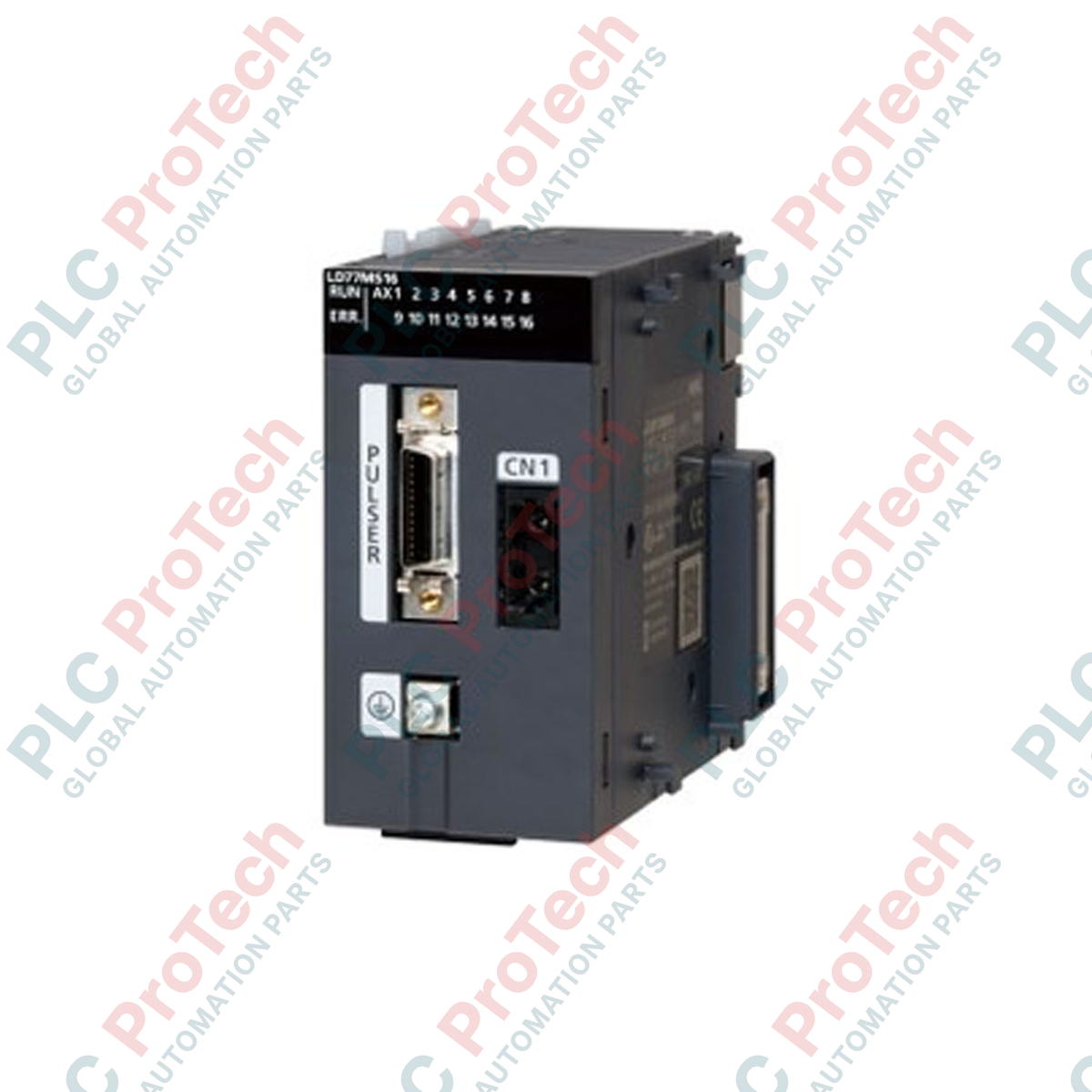
| CN1 (Optical Connector) |
SSCNET III/H loop connection to servo drives (MR-J4-B / MR-J3-B) |
| Front Multi-pin Connector |
Manual pulse generator, external inputs (FLS, RLS, DOG, STOP) |
Empirical Engineering Insights
Alternative Models & Compatibility
While migrating from legacy rack-based platforms like the QD77MS16 (Q Series) to the LD77MS16, key programming architectures remain compatible within GX Works2. However, consider physical module layout differences; the L Series utilizes a rack-free bus connector. Ensure the base system has end covers installed on the final block to prevent communication line instability.
Application Pitfalls & Engineering Notes
Pay strict attention to the 5VDC internal current budget. With a high draws of 0.85A, adding multiple motion or network units onto a single L Series CPU stack can easily overload standard power supplies, leading to intermittent CPU restarts or bus errors. Ensure the power calculation includes all connected expansion modules.
Commissioning & Wiring Tips
Keep SSCNET III/H optical fiber cables within their recommended minimum bending radius (typically 25mm to 30mm depending on cable class). Excessively tight bends attenuate optical signals, causing random network disconnects and "SSCNET communication error" faults on startup. Always clean the optical fiber ends with an approved swab before insertion.
Installation Guidelines
CRITICAL WARNING: Verify that the main power supply and auxiliary circuit feeds are completely de-energized before mounting or removing the module. Attempting to install the module while the bus is active can cause permanent damage to the CPU or motion ASIC.
1
Align the module's hooks with the adjoining L Series module or CPU and press together firmly until the joint locks engage securely.
2
Plug the SSCNET III/H optical fibers into port CN1. Ensure the connector clicks into place to confirm positive locking.
3
Connect external limits and sensor logic wires to the front I/O connector using shielded, twisted-pair cables to prevent signal noise.