Description
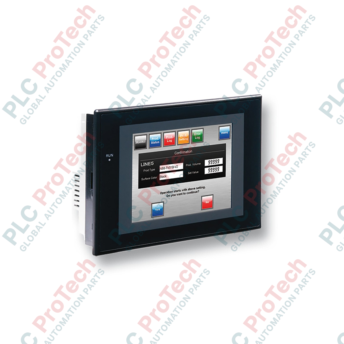
Engineered for distributed machine-level monitoring, the Omron NS5-TQ10B-ECV2 serves as a centralized operator control interface within the premium NS-Series platform. This hardware terminal combines a vibrant 5.7-inch High-Luminance TFT Color LCD with robust communication capabilities, incorporating an integrated 10Base-T Ethernet port and dual serial transceivers. Operating on a standard 24 VDC input, the terminal is designed to withstand harsh factory environments, featuring an IP65f front-face rating and a resilient black protective bezel. With 60 MB of internal memory, it supports complex graphic representations, high-density alarm logging, and seamless CX-Designer configuration integration.
Features
- High-visibility TFT display supporting up to 32,768 colors for realistic CAD-based machine graphics.
- Built-in Ethernet port enabling FTP server capabilities, data transfers, and remote monitoring over TCP/IP.
- Dual independent RS-232C serial ports for direct, simultaneous connections to PLCs, temperature controllers, and barcode readers.
- Extensive 60 MB memory allocation for substantial screen data storage, system recipes, and historic trend logs.
- High-durability LED backlight providing long-term illumination consistency without the degradation risks of legacy CCFL lamps.
Applications
- Automated packaging and cartoning machinery line integration.
- Pumping stations and local water treatment HMI monitoring panels.
- Automotive component assembly verification and testing cells.
- Discrete material handling and sorting system visualization.
Technical Specifications Table
| Parameter |
Specification Value |
| Manufacturer |
Omron |
| Model Number |
NS5-TQ10B-ECV2 |
| Display Type |
5.7-inch High-Luminance TFT Color LCD |
| Resolution |
320 x 240 pixels (QVGA) |
| Backlight |
LED (non-replaceable, service life approx. 50,000 hours) |
| Input Voltage |
24 VDC (Acceptable range: 20.4 to 27.6 VDC) |
| Power Consumption |
15 W maximum |
| Onboard Ethernet |
1x RJ-45 Port (10Base-T) |
| Serial Communications |
2x RS-232C Ports (D-sub 9-pin female) |
| USB Interfaces |
1x USB Type B Slave (for programming download) |
| Internal Project Memory |
60 MB Flash Memory |
| Enclosure Bezel Color |
Black |
| Protection Rating |
IP65f (front panel, panel-mounted) |
| Operating Temperature |
0 to 50 degC |
| Shipping Weight (Calculated) |
1.85 kg |
| Package Dimensions (Calculated) |
245 x 195 x 110 mm |
Connections and Interfaces
| Port / Terminal Block |
Physical Form |
Signal Assignment & Pin Function |
| Serial Port A (CN1) |
D-sub 9-pin Female |
Host Link / NT Link RS-232C communication channel 1 |
| Serial Port B (CN2) |
D-sub 9-pin Female |
Host Link / NT Link RS-232C communication channel 2 |
| Ethernet |
RJ-45 |
10Base-T network interface (FTP, screen data transfer, FINS communications) |
| USB (Slave) |
USB Type B |
Connection to CX-Designer programming PC for screen development and diagnostics |
| Power Input |
M3 Screw Terminals |
Pin 1: +24 VDC | Pin 2: 0 VDC | Pin 3: Functional Ground (FG) |
Empirical Engineering Insights
Alternative Models & Compatibility
The "ECV2" revision represents a major evolutionary step over older NS5-TQ10B-V2 units. The critical distinction lies in the backlight design: the ECV2 employs an integrated solid-state LED configuration, whereas earlier legacy units utilized CCFL tubes driven by high-voltage internal inverters. Project databases generated for older NS5 versions can be converted to run on the ECV2 unit via CX-Designer; simply update the destination hardware designation inside the system properties before transferring. Be aware that color rendering profiles may differ slightly due to the shift from CCFL to LED emission spectrums.
Application Pitfalls & Engineering Notes
Touch-screen matrix degradation is a common physical failure point if these terminals are installed in close proximity to radiant heat sources. While the unit functions up to 50 degC, prolonged internal temperatures exceeding 45 degC inside non-ventilated enclosures can lead to local delamination of the resistive overlay. For panels where ambient internal heat is a constant factor, we recommend installing low-draw convective air systems or cooling fans, maintaining a mandatory 100 mm clearing around the backplate air vents.
Commissioning & Wiring Tips
To prevent grounding-loop failures across serial pathways, ensure the functional ground terminal (FG) is tied back to the main cabinet star-ground point via a heavy-gauge (minimum 2 mm²) stranded green wire. When implementing RS-232C communication lines to CS/CJ-series PLCs, always utilize double-shielded twisted pairs and ground the cable shield on the PLC chassis side only. This layout successfully diverts high-frequency industrial noise away from the NS5 transceiver chips, avoiding intermittent "HMI Communication Timeouts" errors.
Installation Guidelines
CRITICAL WARNING: Isolate the 24 VDC supply and de-energize the entire control panel prior to attempting HMI physical mounting or electrical termination. Executing wiring procedures while power is active can induce voltage spikes, causing permanent logic board destruction.
1
Ensure the panel cutout dimensions measure exactly 184.0 mm (+0.5/-0 mm) wide by 131.0 mm (+0.5/-0 mm) high to achieve an optimal environmental seal.
2
Check that the waterproof rubber sealing gasket is seated uniformly in the front-bezel groove before inserting the HMI terminal into the cutout.
3
Secure the unit into the panel using the provided metal mounting clamps. Tighten the clamping screws evenly to a target torque of 0.5 to 0.6 N-m; over-torqueing may warp the plastic bezel, ruining the IP65f seal.
4
Terminate the 24 VDC lines to the power terminal block, verifying polarity matches the marked terminals before switching on the power.