Product Overview
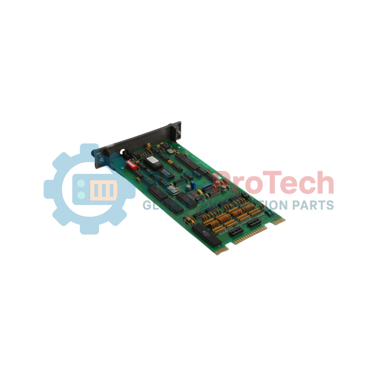
The IMASI02 is a high-density Analog Slave Input module engineered by ABB Bailey for the rugged Infi 90 Process Management System. Functioning as a high-integrity field interface, this card accepts fifteen separate process field signals from specialized sensors and translates them into a digitized format across the system backplane. Automated heavy industrial operations—such as fossil-fuel thermal power generation blocks, chemical processing reactors, and large-scale paper mills—rely on the IMASI02 to gather critical variable feedback. The Multi-Function Processor Module (MFP) analyzes this raw input telemetry to maintain precise control loop execution. Additionally, the module supports bidirectional smart communications, allowing it to route operational commands directly from the MFP or a Smart Transmitter Terminal (STT) down to Bailey Controls smart transmitters. This capability enables remote configuration, speeds up diagnostic routines, and limits unexpected system downtime.
Data Interfacing & Hardware Configuration
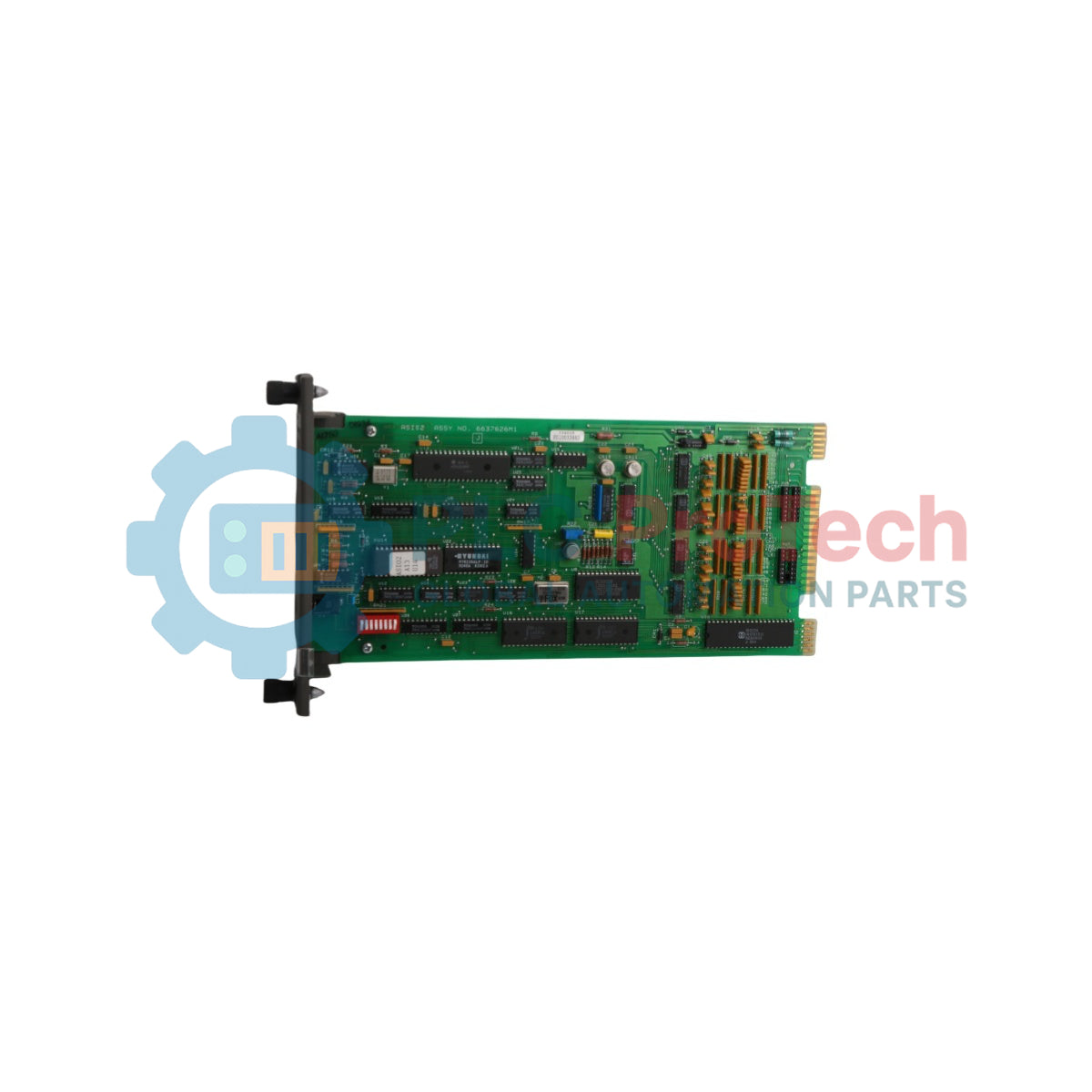
The structural interface paths, bus layout, and internal communication lines of the IMASI02 slave module ensure seamless data delivery inside the chassis rack.
-
Multi-Channel Input Capacity: Features fifteen isolated paths designed to acquire independent analog process variables simultaneously without channel cross-talk.
-
Direct Module Mounting Connection: Plugs directly into the Module Mounting Unit (MMU) backplane via terminal P1 to draw regulated +5 VDC and +/-15 VDC operational power rails.
-
Slave Expander Bus Linkage: Interfaces through connector P2 to bridge local input registers onto the dedicated slave expander bus for high-speed master card polling.
-
Smart Device Communication Routing: Relays complex programming matrices and digital configuration commands from the system master to line-mounted smart field instruments.
-
Diagnostic Verification Cluster: Outfitted with front-facing hardware status LEDs that provide on-site validation codes during loop testing and system troubleshooting.
Technical Performance Standards
| Parameter |
Certified Specification Standard |
| Model Identity |
IMASI02 |
| Brand Manufacturer |
ABB Bailey Controls |
| Control System Line |
Infi 90 / Network 90 DCS Architecture |
| Module Classification |
Analog Slave Input Module (ASI) |
| Signal Input Capacity |
15 Separate Process Field Signal Inputs |
| System Master Compatibility |
Multi-Function Processor Module (MFP) |
| Local Bus Interfacing |
Slave Expander Bus Configuration via P2 |
| Input Operational Voltages |
+5 VDC, +15 VDC, and -15 VDC Regulated Rails via P1 |
| Smart Protocol Bridging |
Bailey Controls Smart Transmitter Terminal (STT) Lines |
| PCB Environmental Protection |
Heavy-Duty Industrial Conformal Coating Layer |
| Operating Temperature Window |
0 to +70 deg C Continuous Environmental Envelope |
| Storage Temperature Bounds |
-40 to +85 deg C Secure Storage Constraints |
| Manufacturing Origin |
United States (USA) |
Industrial System Operation FAQs
How does the IMASI02 module communicate with the main system master module?
The IMASI02 links to its designated master module across the slave expander bus via the rear P2 connector. To establish this communication path, you must install a physical dipshunt on the backplane of the Module Mounting Unit (MMU) across the specific slot lines. If the modules are not located close enough for the bus to bridge them, or if the dipshunt is missing, communication will fail.
What power supply rails are required to drive the internal circuits of this card?
The card draws its electrical power entirely through the backplane P1 connector when seated inside the chassis framework. It requires a regulated supply of +5 VDC alongside stable +/-15 VDC voltage lines to power both the digital processing logic and the analog input conditioning arrays.
Can field engineers calibrate smart transmitters directly through the IMASI02 interface?
Yes. The module supports bidirectional smart signaling. It can relay configuration files and operating commands received from either the Multi-Function Processor Module (MFP) or a handheld Smart Transmitter Terminal (STT) straight to connected Bailey Controls smart field transmitters.
Engineering & Installation Guide
-
Dipshunt Configuration and Slave Expander Placement:
Before sliding the IMASI02 into its assigned slot in the Module Mounting Unit (MMU), verify that the backplane dipshunt is securely installed on the MMU housing. The dipshunt must physically bridge the slave expander bus pins between the input slave card and its corresponding master processor. Group the modules next to each other in the rack layout to maintain clean bus connections and prevent signal reflections.
-
Backplane Grounding and Ribbon Alignment Rules:
Gently slide the card along the slot guide rails until connectors P1 and P2 mate firmly with the backplane board. Do not force the module into place, as misaligned pins can permanently damage the bus lines or short out the +5 VDC and +/-15 VDC power traces. Ensure the chassis frame is properly connected to the single-point plant earth ground to shield the analog conversion chips from high-frequency electromagnetic noise.
-
Signal Insulation Routing and Thermal Protection Protocols:
Route all external analog sensor wires through dedicated, shielded twisted-pair cables to keep ambient inductive noise from distorting the 15 input channels. Connect the cable shields to ground at the termination panel only, and cut them clean at the field instrument side. Keep the panel ventilation slots clear to maintain a stable operating temperature within the certified 0 to +70 deg C window, which prevents thermal drift in the analog-to-digital converter circuits.