


Derivative Action in PID Control Without Noise Problems
Learn what derivative action contributes to a PID loop, why it can amplify measurement noise and setpoint changes, and how filtering, sampling, and staged tests make D tuning safer.
Manufacturer: ABB
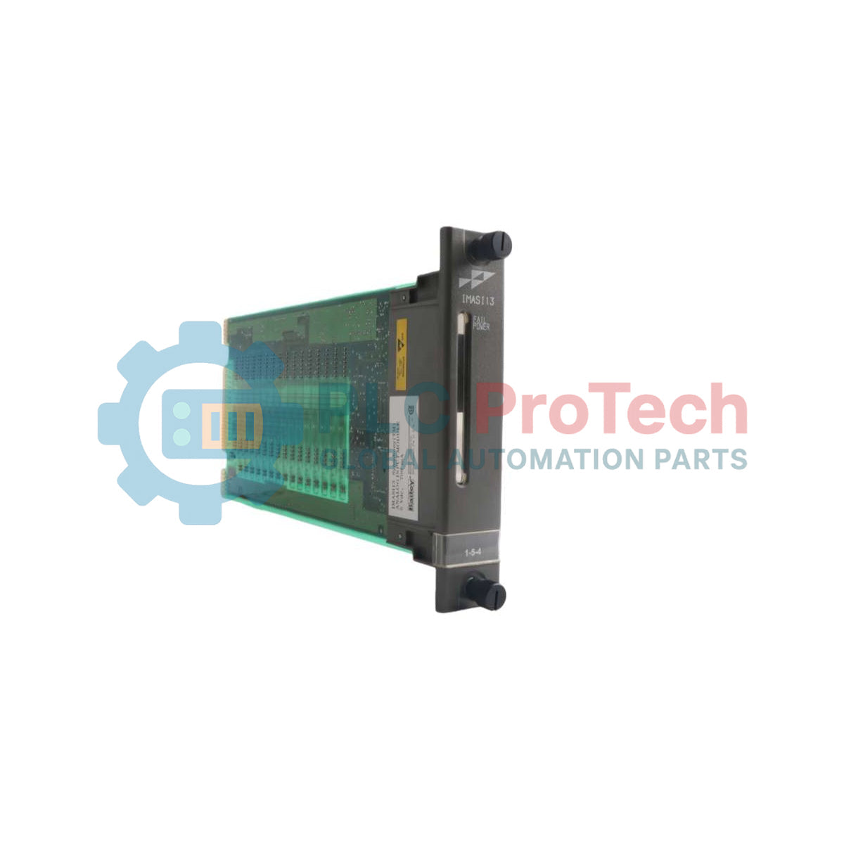
Product No.: IMASI13
Country of origin:Switzerland
Product Type: Analog Input Module
Barcode: 8537101190
Payment: T/T, Western Union
Weight: 1146g
Dimensions: 355.6 mm x 55.4 mm x 279.4 mm (H x W x D)
Shipping port: Xiamen
Warranty: 12 months
The ABB IMASI13 is a high-density, high-resolution analog input module designed for the Symphony Enterprise Management and Control System and fully compatible with legacy INFI 90 OPEN Strategic Enterprise Management Systems. Operating as an intelligent component within the Harmony rack I/O architecture, the IMASI13 interfaces up to 16 independently configured process channels to a Harmony area controller via a parallel, synchronous I/O expander bus.
The primary purpose of the IMASI13 is to condition, isolate, and digitize raw plant signals, incorporating dedicated delta-sigma analog-to-digital converters per channel to deliver an exceptional conversion resolution of 24 bits. It acts as a direct, drop-in replacement for the IMASI03 module, requiring only slight specification updates within function code 216 to accommodate enhanced resolution options. The module eliminates manual calibration overhead by recording factory offset, gain, and nonlinearity coefficients in onboard nonvolatile memory, executing continuous automatic recalibration during normal operation to neutralize component aging and temperature drift.
| Property | Characteristic / Value |
|---|---|
| Manufacturer | ABB Automation Inc. |
| Number of Channels | 16 independently configured channels |
| A-to-D Resolution | 24 bits |
| Conversion Time | 180 msec for all 16 channels |
| Operating Voltage | 5 VDC at 500 mA typical, maximum 750 mA |
| Overvoltage Category | I for circuits above 150V, II for circuits below 150V (IEC 61010-1) |
| Thermocouple Input Types | E, J, K, L, N (14 AWG), N (28 AWG), R, S, T, U, Chinese Type E, Chinese Type S |
| 3-Wire RTD Input Types | 100 ohm platinum (U.S. Lab. Standard, U.S. Industry Standard, European Standard), 120 ohm nickel, 10 ohm copper, Chinese 53 ohm copper |
| Millivolt Input Range | -100 mV to +100 mV, 0 to 100 mV |
| High Level Voltage Range | 1 to 5 VDC, 0 to 5 VDC, 0 to 10 VDC, -10 VDC to +10 VDC (or user-specified within -10 and +10 VDC) |
| Current Input Range | 4 to 20 mA (system or external power) |
| Input Impedance (mV, TC) | 10 MOhm minimum |
| Input Impedance (V, mA) | 100 kOhm minimum |
| Current Accuracy | 0.02% of full scale range |
| High Level Voltage Accuracy | 0.04% of full scale range |
| Low Level Voltage Accuracy | 0.03% of full scale range |
| Resistance Accuracy | 0.05% of full scale range |
| Temperature Effect (0 to 70 degC) | 0.003% of full scale range per degree C maximum |
| Input Settling Time | 1.5 seconds to within 1% after full scale step change |
| Cold Junction Reference Accuracy | $\pm0.5$ degC |
| Software Linearization Accuracy | $\pm0.1$ degC |
| Common Mode Isolation | 250 VDC / V_RMS at 60 Hz (IEC 61010-1, IEC 60255-5, IEC 60060) |
| Insulation Resistance | 100 MOhm minimum at 100/500 VDC |
| Dielectric Strength | 1.4 kVrms/1 min. or 1.95 kV DC/1 min. |
| Impulse Voltage (1.2/50 uS) | +2.55 kVp (Common Mode), +1 kVp (Normal Mode) |
| Normal Mode Rejection (50-60 Hz) | -80 dB minimum |
| Common Mode Rejection (50-60 Hz) | -120 dB minimum |
| Peak or Continuous Voltage | 15 VDC absolute maximum |
| Electrostatic Discharge (ESD) | Contact: $\pm6$ kV, Air: $\pm8$ kV (IEC 61000-4-2, EN 61000-4-2) |
| Ambient Temperature (Operating) | 0 degC to 70 degC (32 degF to 158 degF) |
| Relative Humidity | 5% to 95% up to 55 degC, 5% to 45% at 70 degC (noncondensing) |
| Altitude Range | Sea level to 3 km (1.86 miles) |
| Air Quality | Noncorrosive |
| Mounting Slot Requirements | Occupies a single slot in a standard module mounting unit |
The backplane interface provides electrical connections for input power, expander bus tracking, and plant process loops via three defined edge connectors:
| Connector Pin | Function |
|---|---|
| P1 | Supply voltage inputs (+5 VDC logic power from the MMU backplane) |
| P2 | I/O Expander Bus interface connection (Synchronous parallel communication with the controller) |
| P3 | Input Signal Connections (Interfaces process inputs from the NKAS01/NKAS11 cabling system) |


Global Express Shipping
Returns & Warranty



| Product Image | Model Number / Title | Condition | Availability | Action |
|---|---|---|---|---|

|
Allen-Bradley 1769-IF8 Compact I/O Analog Input Module | Original New | In Stock | View Details |
Global Express Shipping
Returns & Warranty
Orders are processed and delivered Monday-Friday (excluding public holidays).
For full eligibility, restocking fees, and international return details, please view our official Refund & Return Policy .
| Color pattern |
Green
|
| Country of origin |
Switzerland
|
| Power source |
DC Power
|

Learn what derivative action contributes to a PID loop, why it can amplify measurement noise and setpoint changes, and how filtering, sampling, and staged tests make D tuning safer.

A practical guide to segmenting, documenting, and testing industrial Ethernet networks so plant teams can isolate faults quickly, control change, and expand without creating fragile dependencies.

Commission IO-Link systematically from master addressing and port modes through IODD selection, PLC byte mapping, parameter backups, device validation, and failure-injection tests.

A practical PowerFlex braking guide covering regenerative energy, resistor resistance and duty cycle, thermal protection, model-specific parameters, and measured commissioning tests.

An industrial joystick is only the first element in a safe motion command chain. This guide covers sensing choices, wiring, signal validation, PLC logic, restart behavior, and commissioning for...

PID tuning becomes safer when engineers can see how proportional, integral, and derivative actions reshape error, output, and response over time. This guide turns live trends into a disciplined...