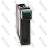
Allen-Bradley 1734-OB4E Point I/O 4-Point Digital Output Module
SKU 1734-OB4E
In stock
No reviews
12-month warranty
Free returns within 30 days
Manufacturer:
Allen-Bradley
Product No.:
1734-OB4E
Country of origin:Singapore
Product Type:
Digital Output Module
Payment:
T/T, Western Union
Weight:
33g
Dimensions:
56.6 x 12.1 x 77.5 mm (H x W x D)
Shipping port:
Xiamen
Warranty:
12 months
Description
The 1734-OB4E is a 24V DC 4-channel sourcing digital output module designed for use within the Allen-Bradley POINT I/O system. The 1734-OB4E features 4 non-isolated, electronically protected outputs organized into a single group. Operating on a nominal 24V DC external power supply, the module provides short circuit and overload protection for connected field loads. The module interfaces across industrial networks using DeviceNet, PROFIBUS, ControlNet, or EtherNet/IP adapters, making it suitable for distributed I/O applications controlling field devices such as solenoids, relays, and indicators.
Features
4 non-isolated sourcing digital output channels in one group
Electronically protected outputs for short circuit and overload conditions
Keyswitch position 1 for mechanical keying on compatible terminal bases
Logic-driven status indicators including 4 yellow output status LEDs, 4 red output fault LEDs, and 2 green/red module/network status LEDs
Removable terminal block (RTB) support allowing module replacement without disturbing field wiring
Applications
Distributed I/O processing on DeviceNet and PROFIBUS networks
Control system expansion via EtherNet/IP and ControlNet adapters
Switching 24V DC industrial loads including actuators, relays, and solenoids
Class I Division 2, Zone 2 hazardous location installations
Technical Specifications
Parameter
Specification
Manufacturer
Allen-Bradley / Rockwell Automation
Model
1734-OB4E
Number of Outputs
4 (1 group of 4), non-isolated, sourcing
On-State Voltage, Min
10V DC
On-State Voltage, Nom
24V DC
On-State Voltage, Max
28.8V DC
On-State Voltage Drop, Max
0.2V DC
On-State Current, Min
1.0 mA per channel
Off-State Leakage, Max
0.5 mA @ 28.8V DC
Output Signal Delay, Off to On / On to Off
0.1 ms max
Output Current Rating, Per Output
1.0 A
Output Current Rating, Max Per Module
3.0 A
Surge Current
2 A for 10 ms, repeatable every 3 s
External DC Power Supply Voltage, Nom
24V DC
External DC Power Voltage Range
10...28.8V DC
External DC Power Supply Current
16 mA
POINTBus Current, Max
75 mA @ 5V DC
Power Dissipation @ 28.8V DC, Max
1.2 W
Thermal Dissipation @ 28.8V DC, Max
4.1 BTU/hr
Isolation Voltage
50V (continuous), reinforced insulation type, tested @ 2500V DC for 60 s field-side to system
DIN Rail Grounding: Ground the module through the DIN rail to chassis ground using zinc-plated chromate-passivated steel DIN rail (Allen-Bradley part number 199-DR1; 46277-3; EN50022). Secure the DIN rail to the mounting surface approximately every 200 mm (7.8 in.) and use end-anchors properly.
Enclosure Requirement: Mount the module inside a Pollution Degree 2 industrial enclosure that meets overvoltage Category II applications. Enclosures must require a tool for interior access.
Keyswitch Setting: Set the orange keyswitch on the mounting base to position 1 by rotating clockwise with a bladed screwdriver prior to inserting the module.
Module Insertion: Ensure the DIN rail locking screw is in the horizontal position before inserting the module straight down into the mounting base until it locks.
Hazardous Area Safety: Remove power or ensure the area is nonhazardous before inserting or removing the module or connecting/disconnecting the removable terminal block (RTB) or wiring.
Wiring Limits: Do not wire more than two conductors on any single terminal.
Compliance and Certifications
c-UL-us (UL Listed Industrial Control Equipment File E65584; UL Listed for Class I Division 2 Group A,B,C,D Hazardous Locations File E194810)
UK and CE (EMC Directive 2014/30/EU, EN 61326-1, EN 61000-6-2, EN 61000-6-4, EN 61131-2; RoHS Directive 2011/65/EU, EN IEC 63000)
RCM (EN 61000-6-4)
Ex (ATEX Directive 2014/34/EU, EN IEC 60079-0, EN IEC 60079-7, II 3G Ex nA IIC T4 Gc, DEMKO 04 ATEX 0330347X, UL22UKEX2478X)
KC (Article 58-2 of Radio Waves Act, Clause 3)
IECEx (IEC 60079-0, IEC 60079-7, Ex ec IIC T4 Gc, IECEx UL 20.0072X)
Morocco (Arrêté ministériel nº 6404-15)
CCC (CNCA-C23-01 CCC: 2020122309111607)
FAQ
What is the keying requirement for installing the module on a terminal base?
The orange keyswitch on the mounting base must be rotated clockwise to position 1 before inserting the module.
What is the maximum output current rating for the device?
The module supports up to 1.0 A per individual output channel and a maximum total output current of 3.0 A across the module.
What status indicators are integrated into the front of the device?
The device features 4 yellow output status LEDs, 4 red output fault LEDs, and 2 green/red LEDs for module and network status.
A practical guide to selecting, wiring and diagnosing DIN-style valve connectors, including form identification, coil voltage, suppression, polarity, sealing, release-time effects and commissioning...
A PLC and a microcontroller can both generate step-and-direction motion, but arc welding exposes major differences in EMC, I/O protection, diagnostics, maintainability, safety integration, and...
Piezo pneumatic valves offer low holding power and fine proportional control, but they are not universal solenoid replacements. This guide covers driver electronics, flow limits, contamination, fail...
Built-in sensor timers can reject chatter, stretch short pulses, and simplify local timing—but they do not replace PLC diagnostics or safety logic. Learn how to apply on-delay, off-delay, and...
Reversing a three-phase motor is more than swapping two leads. This guide covers phase sequence, VFD settings, reversing contactors, encoder feedback, load checks, lockout, and commissioning tests.
Grounding one side of a 24 VDC supply can improve fault detection and voltage reference, while floating circuits support isolation. This guide explains bonding, noise, first-fault behavior, and...
Choosing a selection results in a full page refresh.