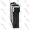
Allen-Bradley 1756-OB16E ControlLogix Digital Output Module
SKU 1756-OB16E
In stock
No reviews
12-month warranty
Free returns within 30 days
Manufacturer:
Allen-Bradley
Product No.:
1756-OB16E
Country of origin:United States
Product Type:
Digital Output Module
Barcode:
8537101190
Payment:
T/T, Western Union
Weight:
300g
Dimensions:
145 mm x 35 mm x 140 mm (H x W x D)
Shipping port:
Xiamen
Warranty:
12 months
Description
The Allen-Bradley 1756-OB16E is a ControlLogix 16-point discrete DC output module designed to interface control signals from a ControlLogix backplane to field-side industrial loads. Operating within a voltage range of 10...31.2V DC with a nominal rating of 12/24V DC, the 1756-OB16E provides electronically fused switching across two isolated groups of 8 channels.
This module executes automated switching operations for devices such as solenoids, relays, actuators, and indicators in industrial control systems. Built with electronic short-circuit and overload protection, the 1756-OB16E maintains continuous system operation and prevents module failure under field fault conditions.
Features
16 discrete output channels organized into 2 groups of 8 points.
Electronic fusing provided per channel group to protect system hardware.
Optical and basic isolation rated at 250V continuous between outputs and backplane, as well as group-to-group.
Electronic, software-configurable module keying to prevent incorrect placement in the chassis.
Configurable output states for Fault mode and Program mode (Hold last state, On, or Off).
Support for output synchronization within 16.7 s max, referenced to Coordinated System Time.
Applications
Factory automation discrete load switching
Solenoid valve control and actuator actuation
Industrial indicator and annunciation panels
Control cabinet relay interface driving
Technical Specifications
Parameter
Specification
Manufacturer
Allen-Bradley / Rockwell Automation
Model
1756-OB16E
Outputs
16 electronically fused (8 points/group)
Voltage Category
12/24V DC source
Operating Voltage Range
10...31.2V DC
Current Draw @ 5.1V DC
250 mA
Current Draw @ 24V DC
2 mA
Total Backplane Power
1.32 W
Power Dissipation, Max
4.1 W @ 60 degC (140 degF)
Thermal Dissipation
13.98 BTU/hr
Off-State Leakage Current Per Point, Max
1 mA per point
On-State Voltage Drop, Max
400 mV DC @ 1 A
Current Per Point, Max
1 A @ 60 degC (140 degF)
Current Per Module, Max
8 A @ 60 degC (140 degF)
Surge Current Per Point, Typical
2 A for 10 ms per point, repeatable every 2 s @ 0 degC (32 degF) @ 24V DC
Load Current, Min
3 mA per point
Output Delay Time (Off to On)
70 us nom / 1 ms max
Output Delay Time (On to Off)
360 us nom / 1 ms max
Scheduled Outputs
Synchronization within 16.7 s max, reference to Coordinated System Time
States in Fault Mode Per Point
Hold last state, On or Off (Off is default)
States in Program Mode Per Point
Hold last state, On or Off (Off is default)
Isolation Voltage
250V (continuous), basic insulation type, outputs-to-backplane, and output group-to-group. No isolation between individual group outputs
Module Keying
Electronic, software configurable
Fusing
Electronically fused per group
Removable Terminal Block
1756-TBNH, 1756-TBSH
RTB Keying
User-defined mechanical
Slot Width
1
Wire Category
1
Enclosure Type Rating
None (open-style)
North American Temperature Code
T4
Operating Temperature
0...60 degC (32...140 degF)
Storage Temperature
-40...+85 degC (-40...+185 degF)
Relative Humidity
5...95% noncondensing
Vibration
2 g @ 10...500 Hz
Operating Shock
30 g
Nonoperating Shock
50 g
ESD Immunity
6 kV contact discharges, 8 kV air discharges
Radiated RF Immunity
10V/m with 1 kHz sine wave 80% AM from 80...2000 MHz; 10V/m with 200 Hz 50% Pulse 100% AM @ 900 MHz; 10V/m with 200 Hz 50% Pulse 100% AM @ 1890 MHz; 3V/m with 1 kHz sine wave 80% AM from 2000...2700 MHz
EFT/B Immunity
+/-4 kV at 5 kHz on signal ports
Surge Transient Immunity
+/-1 kV line-line (DM) and +/-2 kV line-earth (CM) on signal ports
Conducted RF Immunity
10V rms with 1 kHz sine wave 80% AM from 150 kHz...80 MHz
Installation Guidelines
Chassis Mounting: Align the circuit board with the top and bottom guides of the 1756 ControlLogix chassis slot and slide the module until top and bottom locking tabs snap securely.
Electrostatic Discharge Handling: Touch a grounded object or wear an approved grounding wriststrap before handling the unit. Do not touch backplane connectors or internal circuit components.
Enclosure Requirements: Install inside an enclosure properly rated for the specific industrial environment (Pollution Degree 2 indoor locations).
Wiring Terminal Blocks: Field connections require removable terminal blocks (1756-TBNH or 1756-TBSH). Apply user-defined mechanical RTB keying to prevent improper connections.
Hazardous Area Safety: Do not disconnect equipment or field wiring unless power has been removed or the area is known to be nonhazardous.
Compliance and Certifications
cULus: UL Listed Industrial Control Equipment (UL File E65584); UL Listed for Class I, Division 2 Group A, B, C, D Hazardous Locations (UL File E194810)
CE: European Union 2014/30/EU EMC Directive (EN 61326-1, EN 61000-6-2, EN 61000-6-4, EN 61131-2) and 2014/35/EU LVD Directive (EN 61131-2)
RCM: Australian Radiocommunications Act compliant with EN 61000-6-4
Ex / ATEX: European Union 2014/34/EU ATEX Directive compliant with EN IEC 60079-0 and EN IEC 60079-7; II 3 G Ex ec IIC T4 Gc (Certificate UL22ATEX2820X)
IECEx: IECEx System compliant with IEC 60079-0 and IEC 60079-7; II 3 G Ex ec IIC T4 Gc (Certificate IECEx UL 22.0065X)
A PLC and a microcontroller can both generate step-and-direction motion, but arc welding exposes major differences in EMC, I/O protection, diagnostics, maintainability, safety integration, and...
Piezo pneumatic valves offer low holding power and fine proportional control, but they are not universal solenoid replacements. This guide covers driver electronics, flow limits, contamination, fail...
Built-in sensor timers can reject chatter, stretch short pulses, and simplify local timing—but they do not replace PLC diagnostics or safety logic. Learn how to apply on-delay, off-delay, and...
Reversing a three-phase motor is more than swapping two leads. This guide covers phase sequence, VFD settings, reversing contactors, encoder feedback, load checks, lockout, and commissioning tests.
Grounding one side of a 24 VDC supply can improve fault detection and voltage reference, while floating circuits support isolation. This guide explains bonding, noise, first-fault behavior, and...
Seal-in circuits and OTL/OTU instructions can hold the same command, but they fail differently. This guide compares scan behavior, restart risk, troubleshooting, permissives, and safer PLC design...
Choosing a selection results in a full page refresh.