Technical Overview
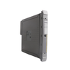
The 1756-OW16I operates as a high-integrity, single-slot digital contact output assembly designed for the Allen-Bradley ControlLogix architecture. Engineered specifically for complex process interlocks in thermal power plants, oil refining tank farms, and heavy mining infrastructure, this module provides sixteen independent, Form A normally open relay contact channels. Each output circuit features complete galvanic isolation from adjacent channels and backplane logic, allowing distinct AC and DC field voltages to operate simultaneously on a single module housing. By eliminating common ground reference pathways and suppressing high-voltage transient cross-talk, this module avoids cascaded channel failures, effectively reducing unexpected field instrumentation downtime in high-vibration and electrically noisy industrial processing environments.
System Architecture and Functional Features
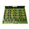
The hardware topology of this digital relay assembly utilizes sixteen discrete, mechanically robust contact relays configured with basic insulation barriers rated for continuous 250 V electrical isolation. It provides native scheduling capabilities, enabling synchronization of contact state transitions within 16.7 ms maximum with reference to the Coordinated System Time (CST) matrix of the Logix backplane. The module features independent, software-configurable state management for both Fault Mode and Program Mode, allowing system engineers to predefine individual channel responses—Hold Last State, Forced On, or Forced Off (default)—to preserve safe field conditions during processor disruption. It requires no internal hardware jumpers, relying instead on electronic software keying via the integrated development environment to prevent erroneous module cross-insertion during field maintenance.
Engineering Specifications
| Specification Metric |
Verified Technical Data |
| Model |
1756-OW16I |
| Brand |
Allen-Bradley |
| Series |
ControlLogix Digital I/O |
| Output Type |
Relay Contacts (16 Form A Normally Open, Individually Isolated) |
| Operating Voltage Window |
5 to 125 VDC / 10 to 240 VAC (50/60 Hz) |
| Current Draw from Backplane |
150 mA @ 5.1 VDC and 150 mA @ 24 VDC |
| Total Backplane Power Consumption |
4.4 W |
| Power Dissipation (Max) |
4.5 W @ 60 deg C (140 deg F) |
| Thermal Dissipation Loading |
15.35 BTU/hour |
| Continuous Contact Ratings (DC) |
1 A @ 5-30 VDC, 0.5 A @ 48 VDC, 0.22 A @ 125 VDC |
| Continuous Contact Ratings (AC) |
1.5 A @ 120 VAC, 0.75 A @ 240 VAC (50/60 Hz) |
| Pilot Duty Classifications |
C300, R150 |
| Minimum Contact Load Current |
10 mA |
| Initial Contact Resistance (Max) |
100 mOhm @ 6 VDC, 1 A |
| Off-State Leakage Current (Max) |
1.5 mA per point |
| Contact Switching Delays |
Off to On: 10 ms max / On to Off: 10 ms max |
| Maximum Switching Frequency |
1 operation per 3 seconds (0.3 Hz at rated load) |
| Isolation Voltage Stability |
250 V continuous (basic insulation type), outputs-to-backplane and output-to-output |
| Compatible Removable Terminal Blocks |
1756-TBCH, 1756-TBNH, 1756-TBSH, 1756-TBS6H |
| Operating Temperature Range |
0 to 60 deg C (32 to 140 deg F) |
| Shock Tolerance |
Operating: 30 G / Non-operating: 50 G |
| Vibration Resistance |
2 G @ 10 to 500 Hz |
| North American Temp Code |
T4A |
| Weight |
0.30 kg (0.66 lbs) |
| Dimensions |
Standard single-slot ControlLogix module envelope |
| Origin |
USA |
FAQs
What is the significance of the 10 mA minimum load current specification on the 1756-OW16I?
The electromagnetic contacts require a minimum wetting current of 10 mA to reliably pierce thin film oxidation layers that naturally develop on the contact surfaces over time. Operating below this current threshold can result in erratic signal continuity or false open-circuit indications despite the relay coil being energized.
Does the 1756-OW16I contain internal fused protection to isolate shorted field loads?
No. The module is not internally fused. To protect the relay contact pathways from overcurrent damage due to field faults, external fusing must be applied. Utilizing a fused Interface Module (IFM) matching publication 1492-TD008 is recommended, though agency certifications are restricted to direct connections via standard ControlLogix Removable Terminal Blocks (RTBs).
Why is the maximum switching frequency limited to 0.3 Hz at rated load?
Because the 1756-OW16I relies on mechanical contacts rather than solid-state triacs or transistors, excessive cycle speeds induce thermal stresses and arc degradation. Restricting the cycle rate to 1 operation per 3 seconds prevents contact overheating and ensures the expected contact lifespan of 300 kHz for resistive loads and 100 kHz for inductive loads.
Field Commissioning and Safety Declarations
-
Arc Mitigation for Inductive Loads: When controlling inductive field elements such as motor starter coils or high-capacity solenoids, external surge suppressors must be installed directly across the load terminals. Use an appropriate RC snubber circuit for AC loops and a freewheeling diode for DC loops. Unsuppressed inductive counter-electromotive force (back-EMF) will accelerate contact degradation, resulting in contact welding and catastrophic module damage.
-
Terminal Assembly Selection and Grounding: Field conductor hookups must be handled using official 36-pin or 20-pin RTBs (e.g., 1756-TBCH, 1756-TBNH). Separate all high-voltage AC current lines from low-voltage DC logic wires by routing them through independent wire ways within the marshalling panel. Ensure the chassis frame maintains a low-impedance connection to the central plant earth ground plane.
-
Live Maintenance Warning (RIUP Restrictions): Although the underlying ControlLogix architecture allows Removal and Insertion Under Power (RIUP) during operational maintenance, executing this process in hazardous locations (Class I Division 2, Temp Code T4A) is dangerous. Field-side supply circuits must be completely isolated and checked for zero voltage before detaching the mechanical terminal blocks or pulling the module from the chassis.