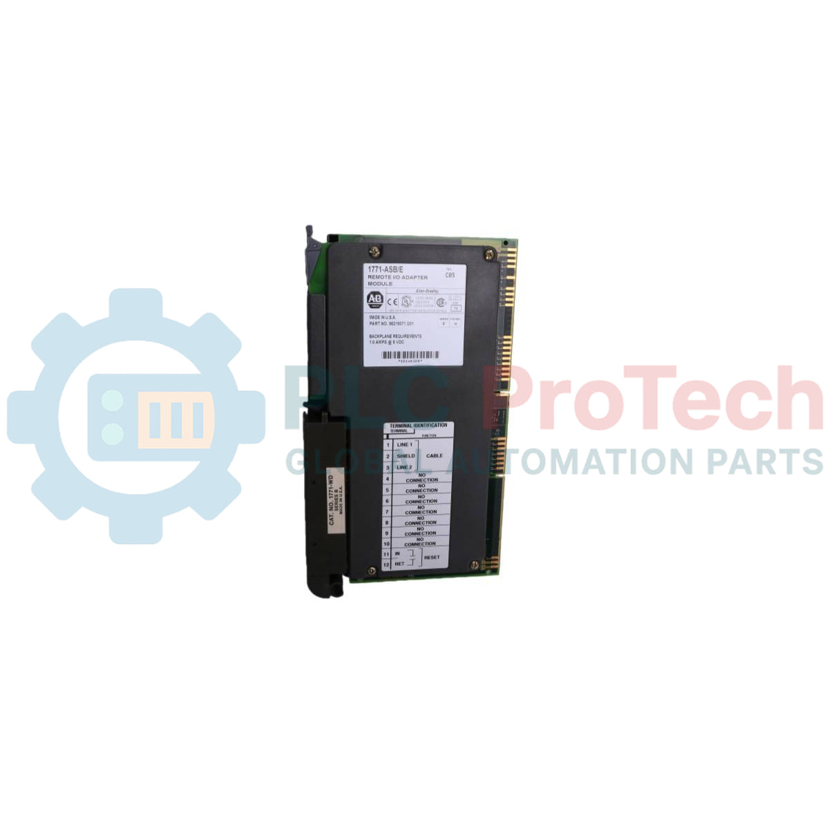
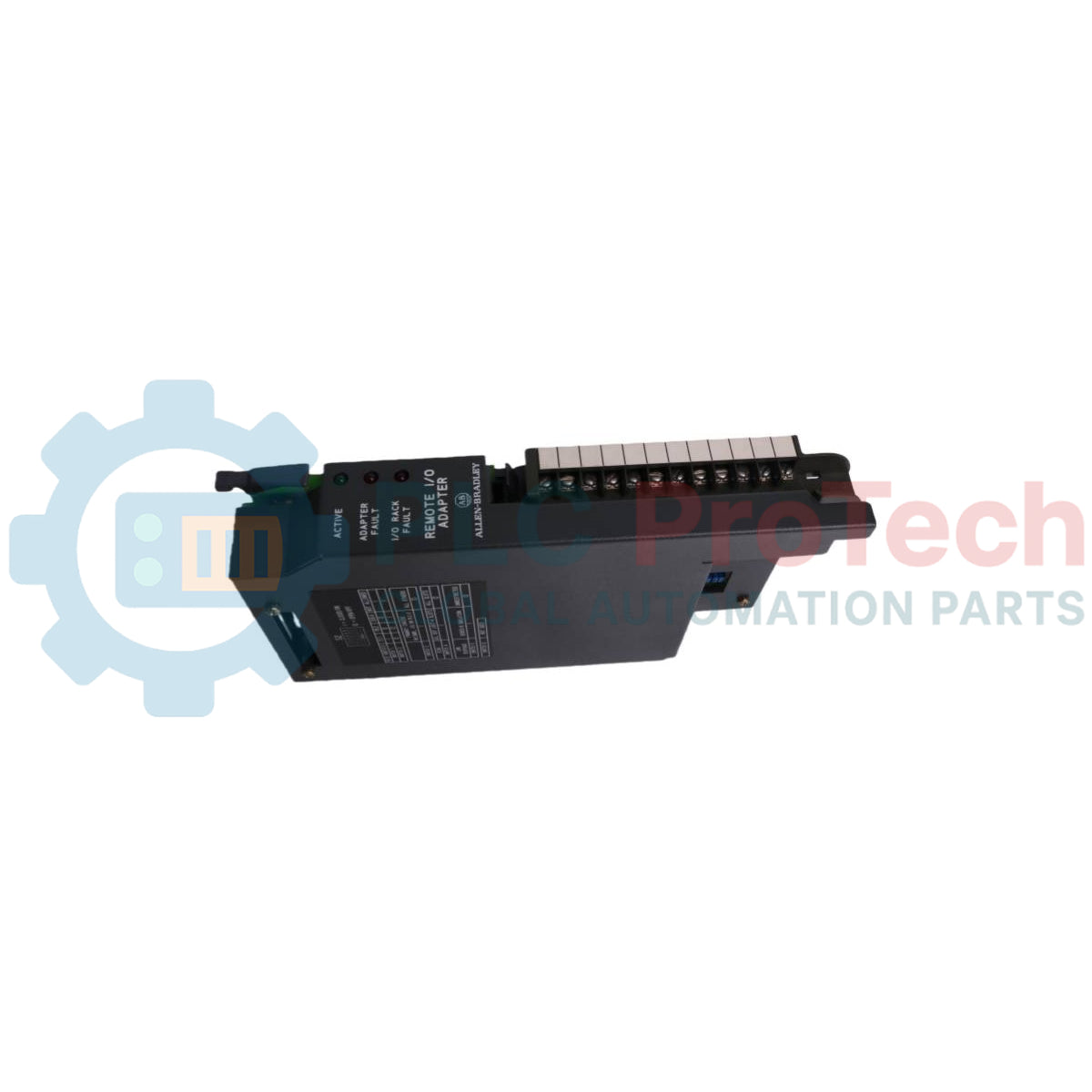
The Allen-Bradley 1771-ASB/E is a remote I/O adapter module that serves as an interface between remote I/O modules and Allen-Bradley programmable controllers. The module receives and sends data from and to the I/O scanner in serial form, and reads and writes data from and to input and output modules in parallel form. It transmits data up to 10,000 cable-feet at 57.6K baud and provides backplane scanning and data transmission up to 2,500 cable-feet at 230.4K baud. The adapter supports any mix of 4, 6, 8, 16, or 32-point I/O modules and accommodates 1/2-slot, 1-slot, and 2-slot I/O addressing methods. It performs I/O configuration checks on power-up to verify module placement and scans all slots in the chassis or all but the last four slots. Additionally, it can emulate Series B adapters to provide system response compatible with 1771-S4A and 1771-S4B scanners.
Features
Transmits data up to 10,000 cable-feet at 57.6K baud and up to 2,500 cable-feet at 230.4K baud.
Supports 1/2-slot, 1-slot, and 2-slot I/O addressing modes.
Supports 4, 6, 8, 16, or 32-point discrete and block-transfer I/O modules.
Emulates Series B adapter link response for compatibility with PLC-2 and PLC-3 scanners.
Verifies I/O module placement on power-up.
Features front-panel ACTIVE, ADAPTER FAULT, and I/O RACK FAULT LED diagnostic indicators.
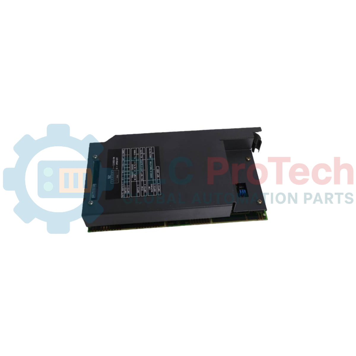
Includes backplane noise immunity retry options selectable via switch assembly.
Applications
Remote I/O chassis interfacing in Allen-Bradley PLC-2, PLC-3, and PLC-5 programmable controller systems.
Distributed industrial control architectures utilizing Universal I/O chassis.
Technical Specifications
Parameter
Specification
Manufacturer
Allen-Bradley
Catalog Number
1771-ASB Series E
Module Type
Remote I/O Adapter Module
Backplane Current
1.0A at 5V DC
Transmission Distance / Baud Rate
10,000 cable-feet at 57.6K baud; 2,500 cable-feet at 230.4K baud
Supported Addressing Modes
1/2-slot, 1-slot, 2-slot
Supported I/O Densities
4, 6, 8, 16, 32 points
Compatible Wiring Arm
1771-WB
Connections/Interfaces
Terminal Pin
Function
1
Blue (Remote I/O Cable)
2
Shield (Remote I/O Cable)
3
Clear (Remote I/O Cable)
4
Connected internally to Terminal 1
5
Connected internally to Terminal 2
6
Connected internally to Terminal 3
7
User-supplied I/O rack restart pushbutton
8
User-supplied I/O rack restart pushbutton
Installation Guidelines
Location & Keying: The 1771-ASB module must be installed in the leftmost slot of the I/O chassis. Key the backplane connectors using keying bands between pins 54–56 for the upper connector and pins 16–18 for the lower connector.
Power Precautions: Remove system power before inserting or removing the module from the I/O chassis to prevent potential circuitry damage.
32-Point / Thermocouple Plug Selection: Access configuration plugs through the side access hole. Set plugs to the left position to enable 32-point I/O modules, or to the right position when using 1771-IX or 1771-IY thermocouple modules.
Module Mounting: Place the module in the plastic guide tracks of the leftmost slot, press firmly to seat it in the backplane connectors, and secure the chassis locking bar.
Termination: For the last adapter module on the link, connect a terminating resistor across terminals 1 (blue) and 3 (clear) on the field wiring arm (150 ohm standard, or 82 ohm for extended node capability at 230.4K baud).
Compliance and Certifications
CE Mark (Directive 89/336/EEC EMC: EN 50081-2, EN 50082-2; Low Voltage Directive 73/23/EEC: EN 61131-2)
FAQ
What power is required from the chassis backplane for the communication module?
The module requires a backplane current of 1.0A at 5V DC.
Which slot in the I/O chassis must the module be installed in?
The module must always be installed in the leftmost slot of the I/O chassis.
What baud rates and cable distances does the adapter module support?
It supports data transmission up to 10,000 cable-feet at 57.6K baud and up to 2,500 cable-feet at 230.4K baud.
How are terminating resistors applied to the remote I/O link?
A terminating resistor must be connected across terminals 1 (blue) and 3 (clear) on the field wiring arm of the last adapter on the link.
A practical replacement guide for the GE Fanuc IC693CPU313, covering its embedded five-slot architecture, memory backup, firmware-dependent capacity and why it cannot use Series 90-30 expansion racks.
A field-focused comparison of Bently Nevada 3500/40M and 3500/42M monitor inputs, channel-pair configuration, rear I/O options, external termination hardware and firmware checks before replacement.
A field checklist for diagnosing Allen-Bradley 1746-NR4 RTD and resistance inputs, including sensor curves, lead compensation, excitation current, filter timing and channel diagnostics.
A field-focused checklist for replacing an Allen-Bradley 1785-L40B or planning a PLC-5/40 migration, covering backups, 1771 I/O mapping, DH+/RIO channels, revision risks and commissioning.
Replacing an Allen-Bradley 1747-SN scanner? Check SLC 500 logical rack and G-file mapping, link speed, cable termination, COMM/FAULT LEDs and hardware series before blaming the module or changing the...