


Replacing ABB DSQC 351: Controller and Network Checks
Checks to record before replacing ABB 3HNE 00006-1 DSQC 351: controller generation, X3/X5/X20/X21 wiring, DeviceNet settings, INTERBUS mapping, and LED states.
Manufacturer: Allen-Bradley
Product No.: 1794-IB16D
Country of origin:United States
Product Type: Digital Sinking Input Modul
Barcode: 8537101190
Payment: T/T, Western Union
Weight: 100g
Dimensions: 46 mm x 94 mm x 53 mm
Shipping port: Xiamen
Warranty: 12 months
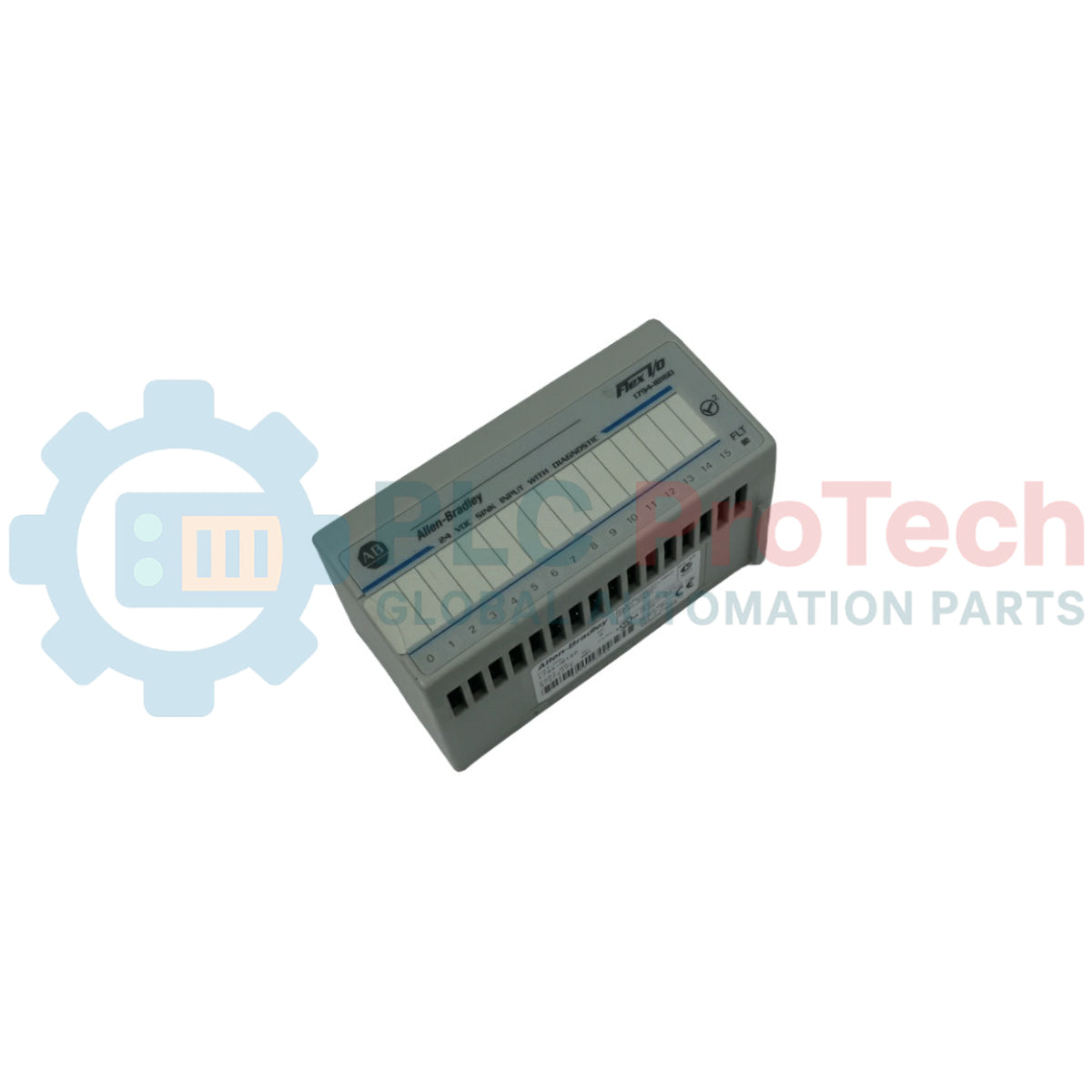
The 1794-IB16D is a high-density discrete hardware component engineered for the FLEX I/O distributed network terminal platform. This 24V DC digital input module is designed to monitor and process binary field conditions while executing comprehensive electronic point-level diagnostics. Operating within a sinking current configuration, the internal circuits route electricity from sourcing field-side instrumentation through its sensing nodes to a centralized common return rail, establishing precise logic state classification and fault isolation across industrial networks.
Equipped with sixteen sinking input channels, the device incorporates advanced electronic diagnostics capable of identifying line faults including open wires, channel short-circuits, and reverse polarity conditions of the external sensor power supply. When an active fault line criteria is met, the 1794-IB16D logs the corresponding error bit into the system memory registers and illuminates a dedicated front-panel indicators array, notifying the centralized master controller without halting adjacent channel operation. The module interfaces over EtherNet/IP, ControlNet, or DeviceNet backplanes, making it typical in critical process installations—such as continuous petrochemical batching, automated automotive assembly lines, municipal water pumping facilities, and packaging automation networks—where immediate sensor line visibility is mandatory to maintain plant safety and uptime.
| Parameter | Specification |
|---|---|
| Manufacturer | Rockwell Automation / Allen-Bradley |
| Brand | FLEX I/O |
| Part Number | 1794-IB16D |
| Module Type | Digital Sinking Input Module with Diagnostics |
| Number of Inputs | 16 Channels, Sinking |
| Nominal Input Voltage | 24V DC |
| On-State Voltage Range | 10V DC to 31.2V DC |
| On-State Current Minimum | 2.0 mA at 10V DC |
| On-State Current Nominal | 8.2 mA at 24V DC |
| On-State Current Maximum | 12.1 mA at 31.2V DC |
| Off-State Voltage Maximum | 5.0V DC |
| Off-State Current Maximum | 1.5 mA |
| Input Impedance Maximum | 3.1 kilohms |
| Sensor Power Voltage Drop | 2.2V DC maximum |
| FlexBus Current Draw | 30 mA at 5V DC |
| Isolation Voltage | 50V continuous, tested at 850V DC for 1 second between user power and system |
| Power Dissipation Maximum | 4.5 W at 31.2V DC |
| Thermal Dissipation Maximum | 15.4 BTU/hour at 31.2V DC |
| Operating Temperature | 0 to 55 degC |
| Storage Temperature | -40 to 85 degC |
| Relative Humidity | 5% to 95% non-condensing |
| Country of Origin | USA |
| Weight | 0.10 kg |
| Dimensions | 46 mm x 94 mm x 53 mm |
| Terminal Base Receptacle Node | Function / Signal Path Allocation |
|---|---|
| Row A: Terminals 0 to 15 | Sinking Input Signal Wire Connections (IN00 to IN15) |
| Row B: Terminals 17 to 32 | Sensor Power Outward Distribution Connections (Sensor Power 0 to 15) |
| Row C: Terminals 36, 38, 40, 42, 44, 46, 48, 50 | Common DC Return Reference Nodes (COM) |
| Row C: Terminals 43, 45, 47, 49 | External +V2 DC Diagnostic Sensor Power Input Terminals |
Engage the upper mechanical retention hooks on the back panel of the module housing onto the upper edge of standard zinc-plated 35 mm DIN tracking. Press down and pivot the bottom portion of the enclosure inward until the spring-activated steel latch assembly snaps securely around the lower rail track lip.
Mount this module exclusively on a pre-installed 1794-TB32 or 1794-TB32S terminal base unit. Rotate the terminal base keyswitch clockwise to position 2 before attempting insertion. Align the physical alignment bar on the bottom face of the module with the guide groove on the base, and press firmly until the side latches seat flush.
Connect discrete input signals to Row A terminals 0 through 15. Connect matching sensor power loops to Row B terminals 17 through 32. For 2-wire field devices, use the designated input and sensor power terminals; for 3-wire field devices, connect the device ground lead to the Row C common nodes. Do not connect signals to terminals 16 or 33.
Supply external 24V DC operational power into the +V2 terminals (43, 45, 47, or 49) on Row C. This separate power path is required to drive the point-level monitoring electronics and execute continuous open-wire and sensor short-circuit diagnostics.
What distinguishes this diagnostic module from the standard 1794-IB16 model?
This module features electronic diagnostic loops that automatically detect open wires, field short-circuits, and external sensor supply reverse polarity conditions.
What terminal base variants must be used with this module?
The module requires the high-density layout provided by the 1794-TB32 or 1794-TB32S terminal base units.
How does the module signal that a sensor wire has been severed?
It triggers a specific channel error bit in the logic register and turns on the front-panel red diagnostic status indicator for that individual channel.
What type of switching configuration is supported by the input points?
The unit features a sinking configuration, meaning it accepts current flowing from external sourcing field instrumentation.
Can this module be hot-swapped during central system run cycles?
Yes, it supports removal and insertion under power, allowing live module swaps without halting network communications on the local rail segment.
What voltage threshold constitutes a logical off-state for an input channel?
An input channel reads as an off-state condition when the incoming voltage drops below 5.0V DC or the loop current drops below 1.5 mA.
Is separate external power required to enable the channel diagnostic loops?
Yes, external 24V DC must be connected to the +V2 terminal paths on Row C to power the onboard field diagnostics.
What is the function of the Row B terminals on the 1794-TB32 base?
They provide individual diagnostic sensor power terminals for each corresponding input channel, allowing the module to monitor current draw per point.
Can this unit process high-voltage alternating current field signals?
No, this module is rated exclusively for direct current applications operating inside a 10V DC to 31.2V DC window.
How are the filter times for the inputs adjusted to filter out switch chatter?
The digital filter times can be configured via programming software to match application signal response needs.


Global Express Shipping
Returns & Warranty


| Product Image | Model Number / Title | Condition | Availability | Action |
|---|---|---|---|---|

|
Allen-Bradley 1794-OB16P FLEX I/O Digital DC Output Module | Original New | In Stock | View Details |

|
Allen-Bradley 1771-IN PLC-5 Digital AC/DC Input Module | Original New | In Stock | View Details |

|
Allen-Bradley 1771-IG TTL Digital DC Input Module | Original New | In Stock | View Details |
Global Express Shipping
Returns & Warranty
Orders are processed and delivered Monday-Friday (excluding public holidays).
For full eligibility, restocking fees, and international return details, please view our official Refund & Return Policy .
| Color pattern |
Greyish White
|
| Country of origin |
United States
|
| Power source |
DC Power
|

Checks to record before replacing ABB 3HNE 00006-1 DSQC 351: controller generation, X3/X5/X20/X21 wiring, DeviceNet settings, INTERBUS mapping, and LED states.

Compare the IC693CPU360 and IC693CPU364 by Ethernet interface, +5 VDC load, memory, rack limits, and replacement checks.

A field-first diagnostic sequence for 1756-OF4 analog output problems: channel mode, removable terminal block, scaling, and controlled electrical checks.

A direct comparison of 1746-OA8 and 1746-OA16 output count, common grouping, backplane current and temperature-derated load limits.

A field checklist for recording the 1761-NET-DNI hardware series, firmware, EDS file, DF1 settings, DeviceNet address and messaging configuration before replacement.

The EL3062 is a 0–10 V EtherCAT terminal. The EL3062-0030 is a 0–30 V variant. This checklist covers identification, scaling and commissioning.