Network Integration Overview
The B&R X20BC8083-EPL (X20BC8083-EPL) is a high-performance real-time industrial Ethernet bus controller engineered to bridge decentralized I/O slices with a centralized POWERLINK network. Deployed across advanced multi-axis motion control applications, synchronized packaging lines, and robotic cell integrations, this module functions as a deterministic fieldbus slave node. By managing cyclic and acyclic data traffic locally on the X20 backplane, the unit enables microsecond-level synchronization across all connected digital, analog, and specialty function slices, preventing network jitter and safeguarding complex production processes from timing discrepancies.
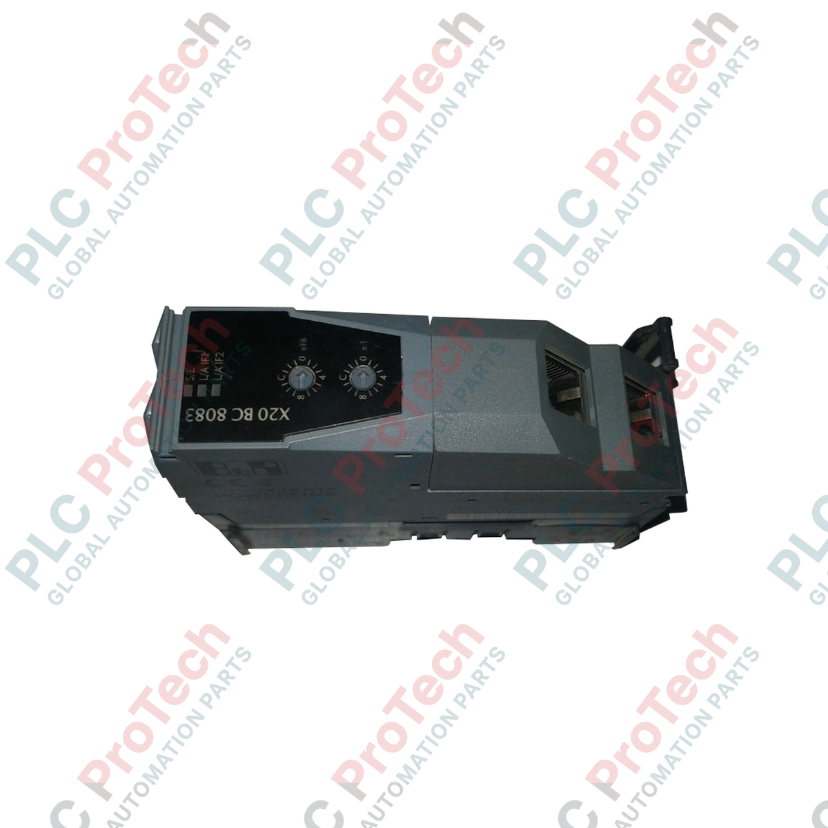
Interface Configuration and Hub Capabilities
This bus controller features one native POWERLINK interface mapped across an integrated 2-port hub infrastructure with two standard RJ45 ports. This hardware layout permits flexible daisy-chain or line network topologies directly on the machine frame, minimizing the need for costly auxiliary industrial switches. For networks requiring advanced branch routing, the controller supports structural expansions via additional X20 hub modules. To adapt to specific mechanical setups, the physical X20 bus base, power supply module, and terminal blocks must be selected and ordered as independent components.
Technical Performance Matrix
| System Parameter |
Functional Specification |
| Model |
X20BC8083-EPL |
| Brand |
B&R Automation |
| Origin |
Austria |
| Protocol Platform |
POWERLINK Real-Time Ethernet |
| Interface Density |
1x POWERLINK Interface, 2x RJ45 Ports |
| Embedded Hardware |
Integrated 2-port hub architecture |
| Expansion Capability |
Supports modular X20 hub expansion cards |
| Required Accessories |
Bus base, power supply module, and terminal block |
| Operating Temperature |
0 to 55 deg C (Standard horizontal mounting) |
| Storage Temperature |
-25 to 85 deg C |
| Relative Humidity |
5 to 95% (Non-condensing) |
| Net Structural Weight |
0.16 kg |
| Shipping Gross Weight |
4.0 kg (Including large-lot industrial packaging) |
System Integration and FAQs
How are node addresses configured on the X20BC8083-EPL network controller?
Node addressing is typically assigned via physical rotary switches located on the accompanying X20 bus base or through the hardware topology tree within B&R Automation Studio. Ensure the designated hexadecimal or decimal node address uniquely matches the identifier expected by the POWERLINK Managing Node (Master CPU) to guarantee proper network initialization.
What action should be taken if the link LED on a port remains unlit when connected to a master controller?
First, verify that the industrial Ethernet cable meets Cat 5e or higher specifications and does not exceed the 100-meter segment limit. Inspect the RJ45 connectors for internal pin contamination or physical damage. If the cable is verified, confirm that the POWERLINK Managing Node is actively broadcasting network cycles and that the controller's firmware matches the project configuration version.
Can standard TCP/IP Ethernet traffic pass through the integrated 2-port hub?
Yes. The POWERLINK protocol incorporates an Asynchronous Phase within its cycle specifically designed to route standard IP-based frames (such as TCP/IP or UDP) across the integrated hub. This enables service technicians to establish web-browser diagnostics or execute remote monitoring queries without disrupting high-speed, deterministic real-time control loops.
Field Commissioning and Installation Directives
-
Component Assembly Sequencing: Do not attempt to mount the electronics module directly to the DIN rail. First, snap the appropriate X20 bus base firmly onto the TS35 rail. Slide the required power supply module onto the left side of the base assembly, and then insert the X20BC8083-EPL electronics block until the mechanical locking clips fully engage. Wire the terminal blocks only after the physical assembly is structurally locked.
-
POWERLINK Cabling and Noise Mitigation: Utilize industrial-grade double-shielded twisted-pair (SF/UTP) cables for both RJ45 network connections. Ground the cable shields directly at the port entry point. Route these communication paths in separate wire tracks away from high-voltage AC lines and variable frequency drive (VFD) motor outputs to protect the real-time Ethernet packets from electromagnetic interference.
-
Expansion Hub Thermal Alignment: When appending modular X20 hub expansion blocks to the controller, recalculate the local power dissipation budget. Ensure the enclosure provides sufficient horizontal spacing—a minimum clearance of 30 mm above and below the module rack—to facilitate natural convection cooling and prevent thermal pocketing from triggering network shutdown faults.