Product Overview
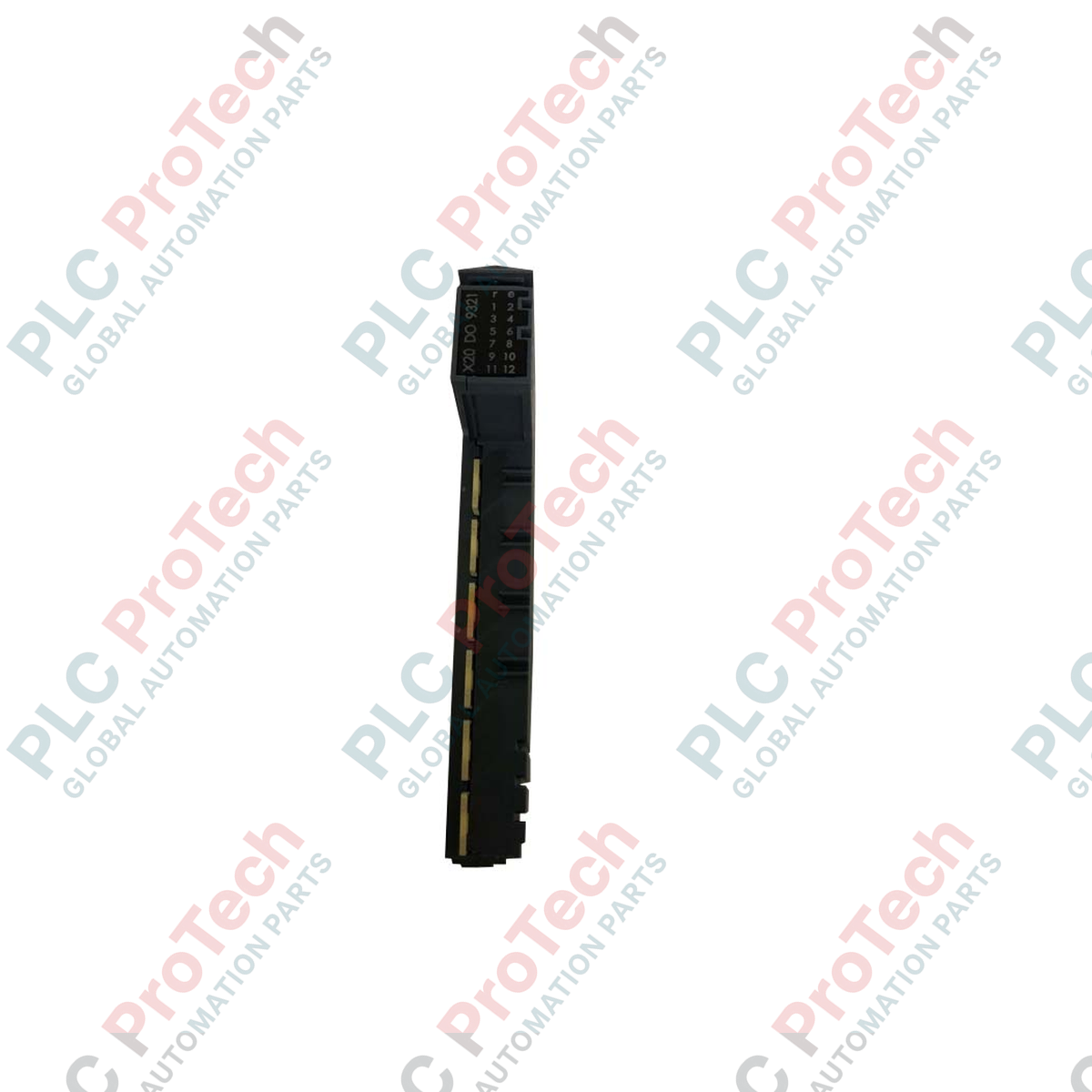
The X20DO9321 (X20DO9321) is a high-density digital output module engineered for the modular B&R X20 System platform. Designed to facilitate robust control signal transmission in industrial automation environments—such as high-speed sorting lines, automated assembly cells, and complex robotic peripheral interfaces—this module provides 12 independent digital output channels. Operating at a standard 24 VDC logic level with a 1-wire connection topology, the unit is optimized for space-efficient control cabinet design. Integrated status LEDs for every channel, operating state, and module health diagnostics allow for instantaneous visual verification, significantly reducing maintenance downtime and simplifying field troubleshooting for automation engineers.
Technical Configuration
This output module is built to ensure reliable performance within the X20 backplane architecture, supporting precise switching for actuators, relays, and pilot valves.
-
High-Density Switching: With 12 independent channels integrated into a single slice, the module offers a high output-to-footprint ratio, essential for applications requiring extensive control connectivity in compact enclosures.
-
1-Wire Architecture: Utilizes a streamlined 1-wire connection design, minimizing the bulk of output cabling and simplifying the physical installation process within the control cabinet.
-
Integrated Diagnostics: The front-facing diagnostic LED matrix provides immediate visual feedback regarding the status of each output channel, current module operational state, and backplane communication health.
-
Seamless Integration: Fully compatible with the B&R X20 bus module architecture, the device ensures low-latency signal distribution, critical for real-time interlock sequences and high-speed process control.
Technical Specifications
| Attribute |
Specifications |
| Model |
X20DO9321 |
| Brand |
B&R (Bernecker + Rainer) |
| Module Type |
Digital Output Module |
| Digital Outputs |
12 Channels |
| Nominal Voltage |
24 VDC |
| Wiring Capability |
1-wire connection |
| Status Indicators |
Individual channel, module state, and operating status LEDs |
| System Compatibility |
B&R X20 System |
| Protection Rating |
IP20 |
| Shipping Weight |
4 kg |
Industrial Hardware FAQs
Does the X20DO9321 provide short-circuit protection for the outputs?
The module is designed with built-in protection features to safeguard the internal switching transistors against common faults. However, when driving inductive loads like solenoid coils or contactors, it is strictly recommended to use an external flyback diode or appropriate suppression to prevent high-voltage transients from feeding back into the module and damaging the output stages.
Can I replace the module without disturbing the field wiring?
Yes. The B&R X20 system allows for the removal and replacement of the electronic module head while leaving the base terminal block wired and mounted on the DIN rail. Always ensure the system is de-energized or the safety-related machine state is satisfied before hot-swapping any I/O module.
What should I check if a specific channel LED is not illuminating when triggered?
First, check the PLC application to confirm that the output bit is being set high. If the bit is set but the LED remains off, verify that the 24 VDC supply rail for the output section is active and that the terminal block connection is secure. If the module status LED indicates an error, consult the diagnostic logs in your Automation Studio project for a specific hardware fault code.
Field Commissioning and Safety Guidelines
Wiring and Cable Management
Use proper wire ferrules for all 1-wire connections to ensure a secure terminal fit. Given the 12-channel density, organize output cables using wire ducts to prevent physical strain on the terminal blocks. When wiring, maintain a clean segregation between 24 VDC control outputs and higher-voltage power lines to prevent induced electrical noise on the output channels.
DIN Rail Mounting and Grounding
The X20 system relies on the metallic DIN rail to establish a local ground reference. Ensure the module is snapped firmly onto a grounded, corrosion-free rail. In environments with high levels of electromagnetic interference, this grounding connection is vital for maintaining signal stability and preventing EMI-related output glitches.
Safety and Interlock Verification
When integrating these outputs into safety-critical control sequences, always verify that the outputs are correctly mapped to your safety logic and that any emergency stop or hard-wired interlock is placed appropriately in the actuator circuit. The diagnostic LEDs serve as an excellent commissioning tool to verify correct logical addressing before introducing power to the downstream mechanical hardware.