Product Overview
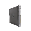
The X20DOF322 (X20DOF322) is a high-density digital output module tailored for the modular B&R X20 System architecture. Designed for streamlined control signal transmission in industrial manufacturing—including automated assembly lines, high-speed material handling, and multi-axis peripheral control—this module provides 16 independent digital output channels. Each channel is configured for source-type wiring with a 1-wire connection topology, significantly reducing cabinet wiring complexity. To ensure robust performance in demanding environments, the module features integrated thermal shutdown protection, built-in freewheeling diodes for inductive load management, and real-time diagnostic monitoring, making it a reliable solution for critical interlock sequences and actuator control.
Technical Configuration
This module balances high output density with advanced diagnostic and protective features to maximize system uptime and hardware longevity.
-
High-Density Switching: Integrates 16 sourcing FET outputs into a single slice, providing an efficient output-to-footprint ratio for compact control panels.
-
Built-in Protection: Features integrated thermal shutdown in the event of overcurrent or short-circuit conditions, with an automatic reset cycle of approximately 10 ms (dependent on module temperature).
-
Inductive Load Management: Equipped with an internal freewheeling diode (clamping at typ. 45 VDC) to effectively handle inductive switching transients, protecting the output stage from damage when driving solenoids or contactors.
-
Advanced Diagnostics: Offers channel-specific diagnostic status with a 10 ms delay for error filtering, and provides "Module run/error" status via both LED indicators and software registers for rapid integration into machine HMI/SCADA diagnostic displays.
Technical Specifications
| Attribute |
Specifications |
| Model |
X20DOF322 |
| Brand |
B&R (Bernecker + Rainer) |
| Output Channels |
16 (Source connection) |
| Nominal Voltage |
24 VDC (-15% / +20%) |
| Nominal Output Current |
0.5 A per channel (8 A total) |
| Switching Delay |
<300 microseconds (0 to 1 / 1 to 0) |
| RDS(on) |
140 milliohms |
| Peak Short-circuit Current |
<3 A |
| Operating Temperature |
-25 to 60 deg C (Horizontal) |
| Protection Rating |
IP20 |
| B&R ID Code |
0xC0EA |
| Shipping Weight |
2 kg |
Industrial Hardware FAQs
Does this module require an external flyback diode for inductive loads?
No. The X20DOF322 includes internal freewheeling diodes specifically designed to clamp inductive energy upon shutdown (typical 45 VDC). This simplifies wiring by eliminating the need for additional suppression components on standard industrial solenoids or small relay coils.
How does the thermal shutdown mechanism behave during a short circuit?
If a short circuit or overcurrent condition is detected, the module enters a thermal shutdown state to protect the FET stage. Once the fault is removed and the module temperature stabilizes, it will automatically attempt to resume operation after a cycle of approximately 10 ms. Constant cycling into shutdown will cause permanent damage; always resolve the root cause of the short circuit immediately.
What is the significance of the 10 ms diagnostic delay?
The 10 ms diagnostic delay is a deliberate filter applied to output monitoring. It ensures that transient power fluctuations or minor contact bounces do not trigger false "error" reports in your PLC diagnostic registers, providing a cleaner and more reliable fault logging process.
Field Commissioning and Safety Guidelines
Required Installation Components
The X20DOF322 is a component-based module. To assemble a functional I/O node, you must order 1x X20TB1F terminal block and 1x X20BM11 bus module separately. Ensure the bus module is mounted on a clean, grounded DIN rail to maintain the specified EMI and backplane communication integrity.
Thermal Derating and Mounting
The module is capable of operating at 60 deg C in a horizontal orientation, but this drops to 50 deg C in a vertical orientation. In high-density cabinets, ensure that the 12.5 mm pitch allows for adequate airflow. If the total aggregate current approaches the 8 A threshold, consider adding forced-air cooling to prevent thermal derating or premature shutdown.
Grounding and Shielding
Despite the 1-wire connection simplicity, the load side remains susceptible to high-frequency noise if routed alongside heavy motor power cabling. Always maintain a minimum separation of 200 mm between output signal bundles and power lines. Ensure the DIN rail is bonded directly to the primary structural earth to provide a low-impedance common-mode return path.