


Implementing 3-Switch XOR Ladder Logic with Internal Bit
Implement a 3-SPST switch XOR light circuit in LogixPro or RSLogix 500 using an internal relay bit. Includes truth tables, boolean equations, and verified.

Designed for seamless integration on the right side of Beckhoff CP6xxx and CP7xxx Control Panels and Panel PCs, the C9900-E875 push-button extension provides a rugged, tactile physical operator interface for 15-inch displays without keyboards. This industrial-grade extension interface bridges physical emergency stop and operational commands directly into the automation control system, enhancing both safety and operator efficiency on the plant floor.
| Parameter | Specification |
|---|---|
| Manufacturer | Beckhoff Automation |
| Model Number | C9900-E875 |
| Compatible Series | CP6x32-00xx & CP7x32-00xx (15-inch without keyboard) |
| Mounting Location | Right side of Control Panel / Panel PC |
| Push-Button Type | 18 x Siemens Signum square (30 x 30 mm) |
| Emergency Stop Button | 1 x Siemens Signum, direct-wired safety channel |
| Signal Transmission | CP-Link or USB (Digital signal for 1st NO contact) |
| Parallel Hardwiring | Terminal row interface for 2nd NO contact |
| Signal Lamp Control | Exclusively via CP-Link or USB communication |
| Status Phase | Service phase (Legacy spare part support) |
| Shipping Weight (Calculated) | 5.0 kg |
As this module is in the official Beckhoff service phase, ensure your target Panel PC or Control Panel has the necessary firmware revision to detect the internal USB/CP-Link controller. Older CP6x32 architectures may require legacy Windows driver profiles to correctly map all 18 push-button indicators.
When active, simultaneous illumination of all 18 signal lamps can load the internal power distribution circuit of the panel HMI. To prevent communication drops over USB, use a high-quality shielded USB connection, or power the host Control Panel through an isolated 24V DC source to avoid ground loop current loops feeding into the signal line.
Always wire the emergency stop button using the direct-wired contact terminal block straight into your safety relay or fail-safe PLC (such as TwinSAFE), rather than relying on the CP-Link/USB fieldbus signal. This satisfies Cat 4 / PL e safety circuit requirements by maintaining hardware-level independence from the HMI OS execution loop.
CRITICAL SAFETY WARNING
Before mounting or wiring the C9900-E875 extension, verify that the host Control Panel and all associated power supplies are fully de-energized. Failure to disconnect physical power can damage the internal CP-Link/USB communication transceiver and cause unexpected safety circuit activations.
Global Express Shipping
Returns & Warranty


Manufacturer: BECKHOFF
Product No.: C9900-E875
Country of origin:Germany
Product Type: HMI Expansion Modules
Payment: T/T, Western Union
Weight: 500g
Dimensions: drawings with dimensions of the push-button e x tensions as AutoCAD DXF file
Shipping port: Xiamen
Warranty: 12 months
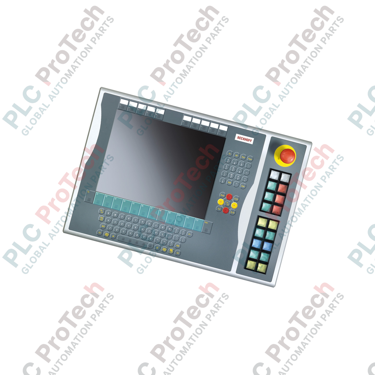
Designed for seamless integration on the right side of Beckhoff CP6xxx and CP7xxx Control Panels and Panel PCs, the C9900-E875 push-button extension provides a rugged, tactile physical operator interface for 15-inch displays without keyboards. This industrial-grade extension interface bridges physical emergency stop and operational commands directly into the automation control system, enhancing both safety and operator efficiency on the plant floor.
| Parameter | Specification |
|---|---|
| Manufacturer | Beckhoff Automation |
| Model Number | C9900-E875 |
| Compatible Series | CP6x32-00xx & CP7x32-00xx (15-inch without keyboard) |
| Mounting Location | Right side of Control Panel / Panel PC |
| Push-Button Type | 18 x Siemens Signum square (30 x 30 mm) |
| Emergency Stop Button | 1 x Siemens Signum, direct-wired safety channel |
| Signal Transmission | CP-Link or USB (Digital signal for 1st NO contact) |
| Parallel Hardwiring | Terminal row interface for 2nd NO contact |
| Signal Lamp Control | Exclusively via CP-Link or USB communication |
| Status Phase | Service phase (Legacy spare part support) |
| Shipping Weight (Calculated) | 5.0 kg |
As this module is in the official Beckhoff service phase, ensure your target Panel PC or Control Panel has the necessary firmware revision to detect the internal USB/CP-Link controller. Older CP6x32 architectures may require legacy Windows driver profiles to correctly map all 18 push-button indicators.
When active, simultaneous illumination of all 18 signal lamps can load the internal power distribution circuit of the panel HMI. To prevent communication drops over USB, use a high-quality shielded USB connection, or power the host Control Panel through an isolated 24V DC source to avoid ground loop current loops feeding into the signal line.
Always wire the emergency stop button using the direct-wired contact terminal block straight into your safety relay or fail-safe PLC (such as TwinSAFE), rather than relying on the CP-Link/USB fieldbus signal. This satisfies Cat 4 / PL e safety circuit requirements by maintaining hardware-level independence from the HMI OS execution loop.
CRITICAL SAFETY WARNING
Before mounting or wiring the C9900-E875 extension, verify that the host Control Panel and all associated power supplies are fully de-energized. Failure to disconnect physical power can damage the internal CP-Link/USB communication transceiver and cause unexpected safety circuit activations.
| Product Image | Model Number / Title | Condition | Availability | Action |
|---|---|---|---|---|

|
Allen-Bradley 2711P-T15C4D9 PanelView Plus 6 Terminal | Original New | In Stock | View Details |
Global Express Shipping
Returns & Warranty
Orders are processed and delivered Monday-Friday (excluding public holidays).
For full eligibility, restocking fees, and international return details, please view our official Refund & Return Policy .
| Country of origin |
Germany
|

Implement a 3-SPST switch XOR light circuit in LogixPro or RSLogix 500 using an internal relay bit. Includes truth tables, boolean equations, and verified.

Integrate Allen-Bradley CompactLogix, Caterpillar ATS, and generators into DeltaV DCS over Modbus RTU. Covers ProSoft MVI69-MCM, Miille DIN266 gateways.

ONS instruction fires but the OTE coil never latches in Studio 5000 because the one-shot is only true for one scan. Use OTL/OTU or seal-in logic instead.

Configure Allen-Bradley Kinetix 5500 servo drives on EtherNet/IP. Covers CIP Sync, IEEE 1588 V2 timing, Stratix selection, DLR topology, and HMI.

A moving-average filter is the sliding-window smoother most instrument engineers drop into DCS and PLC analog paths. Here is how the window works, how N and sample time set lag, and when a...

On Frame 5–9 gas turbines, GE Mark VI and Mark VIe run control as function-block application software. This article maps process, protection, and sequencing functions—and what Toolbox ST access...