Description
Executing low-latency control logic directly at the machine level, the Beckhoff CX5020-0120 delivers high-efficiency processing in a compact, DIN rail-mounted form factor. This embedded industrial controller integrates an Intel Atom Z530 1.6 GHz processor, bridging the gap between high-performance industrial PCs and traditional modular PLC systems. Designed with a fanless architecture and robust thermal dissipation pathways, this controller is engineered to maintain reliability in challenging industrial operating environments without active cooling moving parts.
The unit stands out with its smart I/O terminal adaptation, utilizing a unified backplane interface that automatically detects and interfaces with both E-bus (EtherCAT Terminals) and K-bus (Standard Bus Terminals). With an integrated, maintenance-free 1-second UPS, critical system state variables are safely written to the Compact Flash card during an unexpected loss of primary feed power, preventing file corruption and preserving data integrity across operational cycles.
Key Features
-
Intel Atom Z530 Processor: Provides a stable 1.6 GHz clock frequency for precise, single-core deterministic control loops.
-
Universal I/O Backplane: Supports automatic recognition and dual-compatibility with high-speed E-bus and conventional K-bus communication topologies.
-
Integrated 1-Second UPS: Automatically flushes up to 1 MB of persistent variables to the non-volatile CF media upon detection of main voltage sag.
-
Flexible Communication Stack: Dual independent RJ45 gigabit ports enable physical network separation between upstream factory networks and downstream control subnets.
-
Expansion Slot: Accommodates optional modular fieldbus interfaces for flexible integration into existing multi-protocol environments.
Applications
- High-speed manufacturing execution systems utilizing dense, distributed EtherCAT topologies.
- Embedded machine-level HMI and PLC co-processing via integrated digital video and USB connectivity.
- Remote telemetry and pump station monitoring with requirements for wide temperature endurance.
- De-centralized building automation networks and critical environmental infrastructure controls.
Technical Specifications
| Manufacturer |
Beckhoff Automation |
| Model Number |
CX5020-0120 |
| Processor |
Intel Atom Z530 (1.6 GHz, Single-Core) |
| Volatile Memory |
512 MB RAM (Expandable factory option up to 1 GB) |
| Flash Memory Slot |
Compact Flash slot (128 MB CF card included) |
| Persistent Storage |
1-second UPS (1 MB allocation on CF card) |
| Operating System |
Windows Embedded CE 6 / Windows Embedded Standard 2009 |
| Control Software Support |
TwinCAT 2 runtime, TwinCAT 3 runtime (XAR) |
| TwinCAT 3 Platform Level |
Performance (40) |
| I/O Bus Connection |
E-bus (EtherCAT) or K-bus (Bus Terminals) with automatic detection |
| Max. Bus Output Current |
2 A DC (E-bus / K-bus supply capacity) |
| Supply Voltage |
24 V DC (-15% / +20%) |
| Power Consumption |
13 W maximum (excluding downstream terminal loads) |
| Physical Interfaces |
2 x RJ45 (10/100/1000 Mbps), 1 x DVI-D, 4 x USB 2.0 |
| Environmental Shielding |
IP20 rating |
| Operating Temperature |
-25 degC to +60 degC (-13 degF to +140 degF) |
| Storage Temperature |
-40 degC to +85 degC (-40 degF to +185 degF) |
| Dimensions (W x H x D) |
106 mm x 100 mm x 92 mm |
| Shipping Weight |
3.0 kg (including commercial protective packaging) |
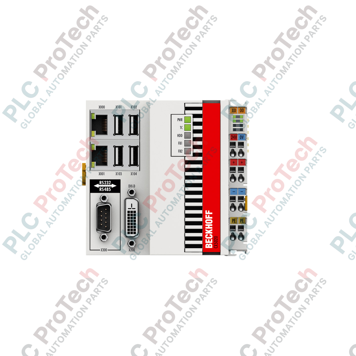
Connections and Interfaces
| Port / Terminal |
Function and Assignment |
| LAN1 / LAN2 (RJ45) |
Independent Gigabit Ethernet ports for connection to TwinCAT control networks or enterprise-level databases. |
| DVI-D |
Direct digital video output interface for localized graphic panel interfaces and visualization displays. |
| USB 1 - 4 |
Four USB 2.0 ports for peripheral integration, programming, and local manual inputs. |
| 24 V DC Terminal |
Primary system power connection with specific contacts for system power and separate fieldbus terminal power. |
Empirical Engineering Insights
Alternative Models & Compatibility
This CPU module is classified under TwinCAT 3 Platform Level 40 (Performance), indicating it cannot run runtime applications compiled for lower platforms (e.g., PL 30) or higher platforms (e.g., PL 50+) without updating the target system settings and corresponding licenses. When replacing an older generation unit, verify that the existing Compact Flash image matches the CPU architecture to avoid boot faults linked to driver mismatches between TwinCAT 2 and TwinCAT 3 runtimes.
Application Pitfalls & Engineering Notes
The integrated 1-second UPS requires a correctly formatted, industrial-grade Compact Flash card with active partitions allocated for persistent data. Do not use consumer-grade CF cards, as they do not support the write-endurance metrics required for high-frequency writes during power cycles. Furthermore, ensure that the total size of your persistent variables does not exceed the 1 MB allocation limit configured in the twin system boot configuration.
Commissioning & Wiring Tips
If the physical connection length of the local E-bus or K-bus slice layout approaches maximum capacity, or if total downstream terminal power draw exceeds the 2 A internal supply threshold, you must insert an auxiliary power feed terminal (such as the EL9400 or KL9400 module) to maintain signal integrity and avoid communication drops.
Installation Guidelines
CRITICAL WARNING
Disconnect all power feeds from the system before initiating hardware mounting, terminal attachment, or interface connection. Confirm that internal capacitive charges have completely dissipated before handling internal components or exchanging the Compact Flash card. Failure to adhere to these safe installation practices may result in physical damage to the controller circuitry or unstable system states.
1
Mount the CPU module vertically on a standard 35 mm DIN rail (EN 60715) to ensure optimal passive convective airflow through the top and bottom cooling slots. Do not block these pathways.
2
Ensure the DIN rail grounding contact is connected to a low-impedance master ground system to mitigate electromagnetic interference and high-frequency noise.
3
Firmly slide downstream I/O modules (E-bus or K-bus terminals) onto the right-hand bus interface. Verify that the physical slide locks secure the modules sequentially.
4
Connect a regulated 24 V DC power supply to the main input terminals. Prior to cycling power, verify that polarity matches the terminal diagram.