


Implementing 3-Switch XOR Ladder Logic with Internal Bit
Implement a 3-SPST switch XOR light circuit in LogixPro or RSLogix 500 using an internal relay bit. Includes truth tables, boolean equations, and verified.

Designed to deliver highly precise current-controlled modulation within distributed control networks, the Beckhoff EL2535-0050 functions as a dual-channel pulse-width modulation (PWM) output terminal for 24 V DC applications. This compact 12 mm module modulates inductive loads up to 50 mA with a default switching frequency of 30 kHz. Featuring integrated push-pull outputs and two auxiliary 24 V DC digital inputs, it enables responsive closed-loop control of thermoelectric coolers, miniature DC motors, and proportional valves directly on the EtherCAT segment.
| Parameter | Value / Specification |
|---|---|
| Manufacturer | Beckhoff Automation GmbH & Co. KG |
| Model Number | EL2535-0050 |
| Connection Technology | PWM output, push-pull outputs |
| Number of Outputs | 2 |
| Nominal Voltage | 24 V DC (-15% / +20%) |
| Load Type | Inductive (greater than 1 mH) |
| Maximum Output Current | ±50 mA |
| Short-Circuit Current | Less than 500 mA typical |
| PWM Clock Frequency | 30 kHz default |
| Duty Factor | 0% to 100% (current-controlled) |
| Resolution | 10 bit |
| E-Bus Current Consumption | Typical 110 mA |
| Power Contacts Current Consumption | Typical 30 mA + load |
| Process Image Bit Width | 48 inputs/outputs (2 x 16 bit data, 2 x 8 bit control/status) |
| Digital Inputs | 2 x digital 24 V inputs |
| Electrical Isolation | 500 V (E-bus / field potential) |
| Operating Temperature | 0 to +55 degC |
| Storage Temperature | -25 to +85 degC |
| Relative Humidity | 95%, non-condensing |
| Protection Class | IP20 |
| Approvals & Markings | CE, UL, ATEX (II 3 G Ex nA IIC T4 Gc), cFMus Class I Div 2 |
| Country of Origin | Germany |
| Net Weight | 50 g |
| Shipping Weight (Calculated) | 0.15 kg |
| Dimensions (W x H x D) | 12 mm x 100 mm x 68 mm |
| Package Dimensions (Calculated) | 120 mm x 80 mm x 25 mm |
| Terminal Point | Signal Assignment | Description |
|---|---|---|
| 1 | PWM Output 1 (+) | Positive connection for PWM Channel 1 |
| 5 | PWM Output 1 (-) | Negative connection (return) for PWM Channel 1 |
| 2 | PWM Output 2 (+) | Positive connection for PWM Channel 2 |
| 6 | PWM Output 2 (-) | Negative connection (return) for PWM Channel 2 |
| 3 | Digital Input 1 | 24 V DC auxiliary digital input for feedback loop 1 |
| 7 | Digital Input 2 | 24 V DC auxiliary digital input for feedback loop 2 |
| 4 | +24 V DC Power Contact | Internal feed connection to positive power rail |
| 8 | 0 V DC Power Contact | Internal feed connection to negative power rail |
Unlike the standard voltage-controlled PWM terminal counterparts, the specialty current-controlled EL2535-0050 regulates output current directly to compensate for temperature-dependent coil resistance variations. Ensure TwinCAT 2.11 (or higher) is configured with the correct XML device description (ESI) file to avoid driver mismatch faults during hardware scanning.
This terminal requires a minimum inductive load of 1 mH. Connecting highly capacitive or purely resistive loads with low inductance values can cause high-frequency oscillations, trigger internal short-circuit limits (under 500 mA), and prevent steady current regulation. In high-density mounting arrays, ensure vertical installation alignment to allow adequate passive thermal dissipation across the polycarbonate terminal housing.
Due to the 30 kHz carrier frequency, we advise utilizing shielded twisted-pair (STP) cabling for connection to the actuator coils. Run the shield to an external grounding clamp (such as the Beckhoff KL9080 shield terminal) as close to the entry point of the electrical cabinet as possible to prevent electromagnetic interference from bleeding into parallel low-voltage analog signals.
CRITICAL WARNING
Isolate all 24 V DC field-side power contacts and standard E-bus power supplies before installing, removing, or wiring any EtherCAT terminals. Electrostatic discharge and hot-swapping can damage sensitive internal bus components.
Align the terminal side-by-side using the double slot-and-key system, then slide it firmly onto a standard 35 mm DIN rail (conforming to EN 60715) until the lock clicks.
Strip wire leads to exactly 8 to 9 mm. Use a flathead screwdriver to depress the spring-actuated terminal mechanism, insert the wire, and release to secure. Solid or ferruled conductors can be pushed directly.
Verify connection cross-sections: use AWG 28 to 14 for solid/stranded wires, and AWG 26 to 16 for wires terminated with ferrules.
Global Express Shipping
Returns & Warranty


Manufacturer: BECKHOFF
Product No.: EL2535-0050
Country of origin:Germany
Product Type: EtherCAT Terminals
Payment: T/T, Western Union
Weight: 2000g
Dimensions: 120 mm x 80 mm x 25 mm
Shipping port: Xiamen
Warranty: 12 months
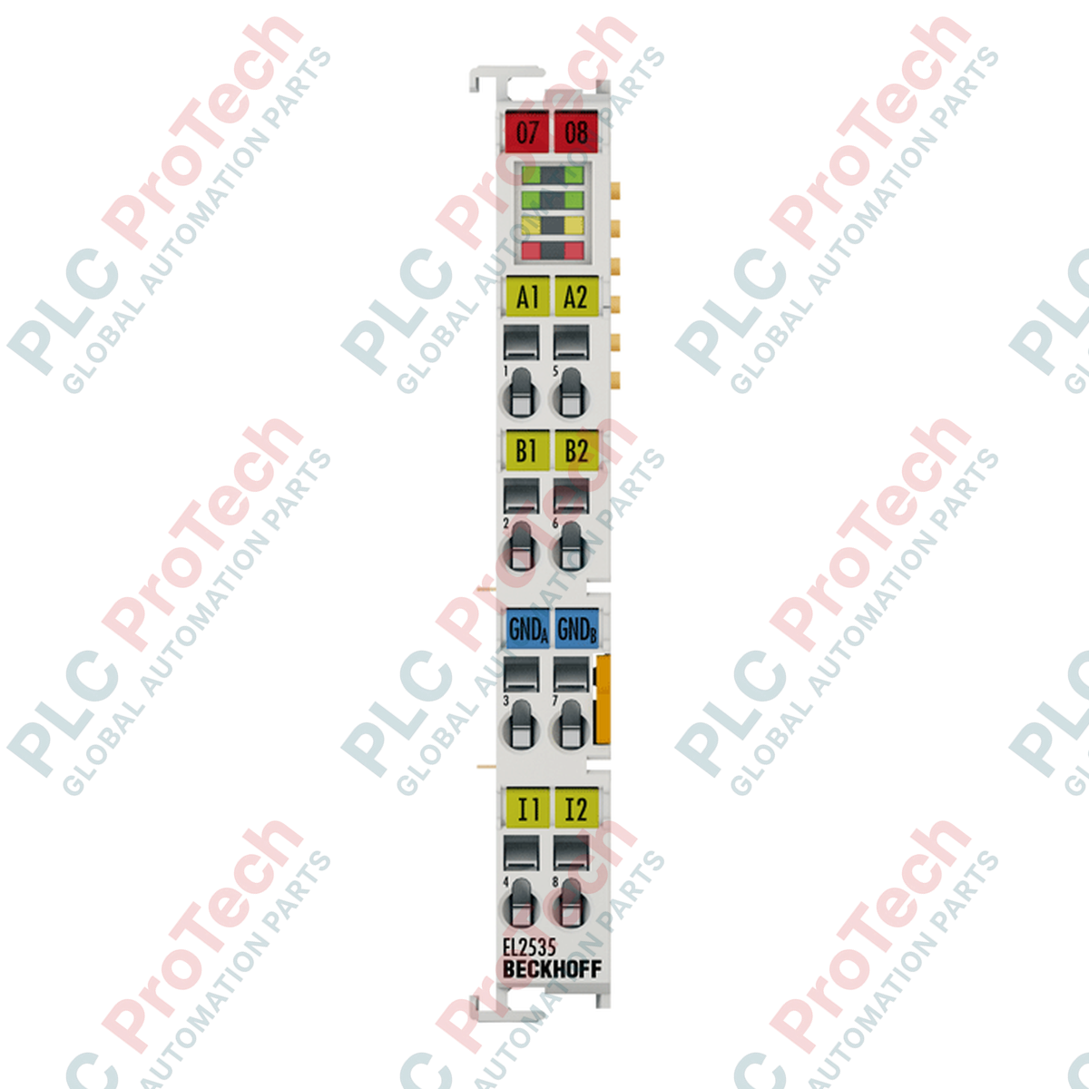
Designed to deliver highly precise current-controlled modulation within distributed control networks, the Beckhoff EL2535-0050 functions as a dual-channel pulse-width modulation (PWM) output terminal for 24 V DC applications. This compact 12 mm module modulates inductive loads up to 50 mA with a default switching frequency of 30 kHz. Featuring integrated push-pull outputs and two auxiliary 24 V DC digital inputs, it enables responsive closed-loop control of thermoelectric coolers, miniature DC motors, and proportional valves directly on the EtherCAT segment.
| Parameter | Value / Specification |
|---|---|
| Manufacturer | Beckhoff Automation GmbH & Co. KG |
| Model Number | EL2535-0050 |
| Connection Technology | PWM output, push-pull outputs |
| Number of Outputs | 2 |
| Nominal Voltage | 24 V DC (-15% / +20%) |
| Load Type | Inductive (greater than 1 mH) |
| Maximum Output Current | ±50 mA |
| Short-Circuit Current | Less than 500 mA typical |
| PWM Clock Frequency | 30 kHz default |
| Duty Factor | 0% to 100% (current-controlled) |
| Resolution | 10 bit |
| E-Bus Current Consumption | Typical 110 mA |
| Power Contacts Current Consumption | Typical 30 mA + load |
| Process Image Bit Width | 48 inputs/outputs (2 x 16 bit data, 2 x 8 bit control/status) |
| Digital Inputs | 2 x digital 24 V inputs |
| Electrical Isolation | 500 V (E-bus / field potential) |
| Operating Temperature | 0 to +55 degC |
| Storage Temperature | -25 to +85 degC |
| Relative Humidity | 95%, non-condensing |
| Protection Class | IP20 |
| Approvals & Markings | CE, UL, ATEX (II 3 G Ex nA IIC T4 Gc), cFMus Class I Div 2 |
| Country of Origin | Germany |
| Net Weight | 50 g |
| Shipping Weight (Calculated) | 0.15 kg |
| Dimensions (W x H x D) | 12 mm x 100 mm x 68 mm |
| Package Dimensions (Calculated) | 120 mm x 80 mm x 25 mm |
| Terminal Point | Signal Assignment | Description |
|---|---|---|
| 1 | PWM Output 1 (+) | Positive connection for PWM Channel 1 |
| 5 | PWM Output 1 (-) | Negative connection (return) for PWM Channel 1 |
| 2 | PWM Output 2 (+) | Positive connection for PWM Channel 2 |
| 6 | PWM Output 2 (-) | Negative connection (return) for PWM Channel 2 |
| 3 | Digital Input 1 | 24 V DC auxiliary digital input for feedback loop 1 |
| 7 | Digital Input 2 | 24 V DC auxiliary digital input for feedback loop 2 |
| 4 | +24 V DC Power Contact | Internal feed connection to positive power rail |
| 8 | 0 V DC Power Contact | Internal feed connection to negative power rail |
Unlike the standard voltage-controlled PWM terminal counterparts, the specialty current-controlled EL2535-0050 regulates output current directly to compensate for temperature-dependent coil resistance variations. Ensure TwinCAT 2.11 (or higher) is configured with the correct XML device description (ESI) file to avoid driver mismatch faults during hardware scanning.
This terminal requires a minimum inductive load of 1 mH. Connecting highly capacitive or purely resistive loads with low inductance values can cause high-frequency oscillations, trigger internal short-circuit limits (under 500 mA), and prevent steady current regulation. In high-density mounting arrays, ensure vertical installation alignment to allow adequate passive thermal dissipation across the polycarbonate terminal housing.
Due to the 30 kHz carrier frequency, we advise utilizing shielded twisted-pair (STP) cabling for connection to the actuator coils. Run the shield to an external grounding clamp (such as the Beckhoff KL9080 shield terminal) as close to the entry point of the electrical cabinet as possible to prevent electromagnetic interference from bleeding into parallel low-voltage analog signals.
CRITICAL WARNING
Isolate all 24 V DC field-side power contacts and standard E-bus power supplies before installing, removing, or wiring any EtherCAT terminals. Electrostatic discharge and hot-swapping can damage sensitive internal bus components.
Align the terminal side-by-side using the double slot-and-key system, then slide it firmly onto a standard 35 mm DIN rail (conforming to EN 60715) until the lock clicks.
Strip wire leads to exactly 8 to 9 mm. Use a flathead screwdriver to depress the spring-actuated terminal mechanism, insert the wire, and release to secure. Solid or ferruled conductors can be pushed directly.
Verify connection cross-sections: use AWG 28 to 14 for solid/stranded wires, and AWG 26 to 16 for wires terminated with ferrules.
Global Express Shipping
Returns & Warranty
Orders are processed and delivered Monday-Friday (excluding public holidays).
For full eligibility, restocking fees, and international return details, please view our official Refund & Return Policy .
| Country of origin |
Germany
|

Implement a 3-SPST switch XOR light circuit in LogixPro or RSLogix 500 using an internal relay bit. Includes truth tables, boolean equations, and verified.

Integrate Allen-Bradley CompactLogix, Caterpillar ATS, and generators into DeltaV DCS over Modbus RTU. Covers ProSoft MVI69-MCM, Miille DIN266 gateways.

ONS instruction fires but the OTE coil never latches in Studio 5000 because the one-shot is only true for one scan. Use OTL/OTU or seal-in logic instead.

Configure Allen-Bradley Kinetix 5500 servo drives on EtherNet/IP. Covers CIP Sync, IEEE 1588 V2 timing, Stratix selection, DLR topology, and HMI.

A moving-average filter is the sliding-window smoother most instrument engineers drop into DCS and PLC analog paths. Here is how the window works, how N and sample time set lag, and when a...

On Frame 5–9 gas turbines, GE Mark VI and Mark VIe run control as function-block application software. This article maps process, protection, and sequencing functions—and what Toolbox ST access...