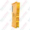
Product Overview
The EL3044 (EL3044) EtherCAT Terminal processes analog control signals in the range from 0 to 20 mA with a 12-bit resolution. Operating on the high-speed E-bus backplane protocol, this 4-channel, single-ended analog input module is engineered for compact control topologies where multiple current loops must be monitored simultaneously.
Deployable across heavy industrial environments—such as marine propulsion monitoring, oil refinery logistics, and water treatment infrastructure—the module delivers exceptional signal density while ensuring high galvanic isolation. By integrating four standard 0 to 20 mA loops into a single 12 mm housing, the terminal optimizes cabinet real estate, simplifies wiring overhead, and provides the steady data reliability needed to lower factory downtime.
Circuit Topology and Signal Configuration
The EL3044 features a single-ended technology design, routing four independent input channels back to a common internal ground reference. The module presents a typical internal input resistance of 85 Ohm, keeping voltage drops minimal across active current loops, and boasts a maximum dielectric strength rating of 30 V.
The input conversion sequence runs via a high-speed multiplexer structure with a default conversion time of 0.625 ms. Advanced internal signal conditioning features allow engineers to activate configurable digital filters (FIR or IIR variants) directly at the hardware layer, enabling precise suppression of high-frequency electrical noise before passing data onward. The 12-bit raw values are mapped using a 16-bit presentation format within the 16-byte process image to maximize data compatibility with various PLC programming standards.
Technical Specifications
| Parameter |
Specifications |
| Model |
EL3044 |
| Brand |
BECKHOFF |
| Origin |
Germany |
| I/O Technology |
EtherCAT Terminal (E-bus powered) |
| Number of Inputs |
4 single-ended channels |
| Signal Current Range |
0 to 20 mA |
| Internal Resistance |
Typ. 85 Ohm |
| Input Filter Limit Frequency |
1 kHz |
| Resolution |
12 bit (16 bit presentation including sign) |
| Conversion Time |
0.625 ms (default setting, multiplexed) |
| Measuring Error |
Less than +/-0.3 % (relative to full scale value) |
| Electrical Isolation |
500 V (E-bus to signal voltage) |
| Current Consumption (E-bus) |
Typ. 130 mA |
| Process Image Bit Width |
Inputs: 16 bytes |
| Dimensions (W x H x D) |
12 mm x 100 mm x 68 mm |
| Weight |
Approx. 60 g |
| Operating Temperature |
-25 to +60 deg C |
| Storage Temperature |
-40 to +85 deg C |
| Environmental Protection |
IP20 |
| Hazardous Area Approvals |
ATEX, IECEx, cFMus |
| ATEX Certification |
II 3 G Ex nA IIC T4 Gc |
| cFMus Classification |
Class I, Division 2, Groups A, B, C, D; Class I, Zone 2, AEx ec IIC T4 Gc |
Product FAQs
What is the functional difference between single-ended and differential analog inputs?
Single-ended modules like the EL3044 route all incoming signal currents through a shared internal reference ground point. This design allows for a higher channel density within a smaller footprint but requires all connected field transmitters to share a common ground potential to prevent ground loop errors. Differential inputs isolate each channel's positive and negative lines completely.
Can the process image layout be adjusted to conserve EtherCAT network bandwidth?
Yes. The EL3044 supports both standard and compact process image selections. Through the TwinCAT System Manager, users can switch to the compact image variant, which strips out additional status and diagnostic bits, leaving only the essential raw analog data to minimize cyclic bus load.
How do the activatable FIR and IIR digital filters assist in field operation?
The integrated Finite Impulse Response (FIR) and Infinite Impulse Response (IIR) filters allow for custom notch filtering to attenuate specific electrical noise frequencies, such as 50 Hz or 60 Hz line hum from nearby high-voltage machinery. This digital preprocessing provides cleaner data inputs for downstream PID control loops.
Field Termination Guidelines and Safety Standards
-
Cage Clamp Termination Protocol: Open the integrated tension clamps using a standard flat-blade technical screwdriver. Strip signal conductors precisely to 8 to 9 mm. The terminal pins accommodate solid (e) or stranded (st) wires from AWG 28 to 14, or ferrule-insulated (f) lines from AWG 26 to 16. Ensure all wire strands are fully contained within the clamp to prevent short circuits.
-
Mechanical Interlocking and Grounding: Snap the module vertically onto a 35 mm DIN rail conforming to EN 60715. Use the integrated double slot and key connection system to slide and lock the terminal securely into the existing I/O stack. To safeguard the 500 V galvanic isolation barrier, ensure the cabinet's grounding rail is firmly tied to a low-impedance earth ground.
-
Hazardous Area Safe Operation: This device carries extensive ATEX, IECEx, and cFMus Class I, Division 2 certifications for explosive atmospheres. When deployed in Zone 2 environments, the equipment must reside inside an IP54-rated control enclosure. Never connect, disconnect, or actuate terminal wires while the main system power supply is live.