Product Overview
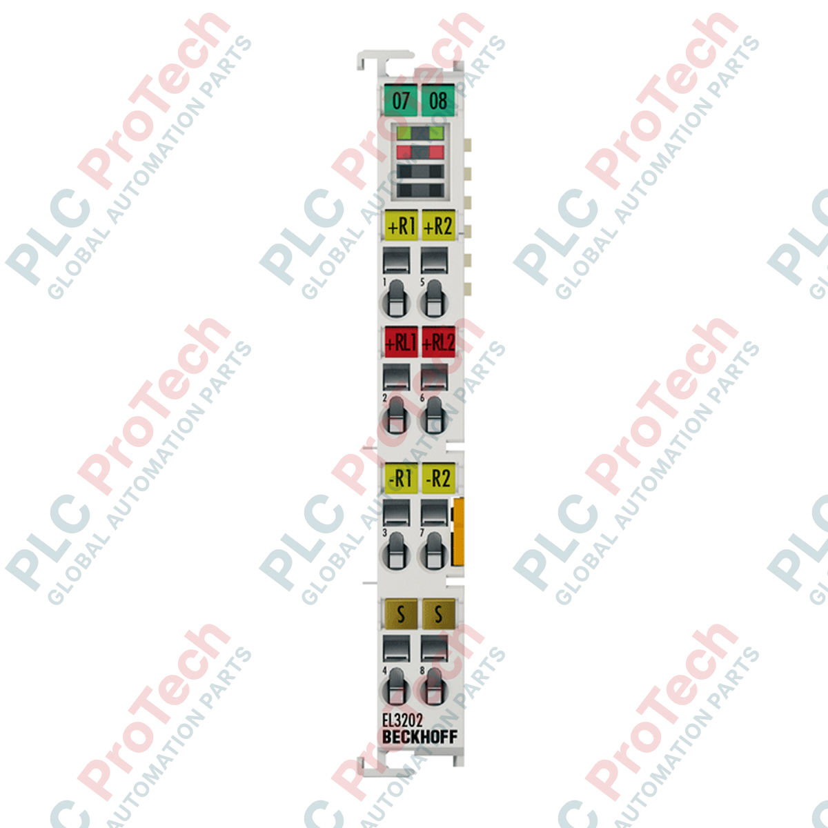
The EL3202 (EL3202) EtherCAT Terminal is a high-precision, 2-channel analog input module engineered for direct resistance temperature detector (RTD) connection. Operating on the high-speed EtherCAT protocol, this terminal accommodates extensive sensor types including Pt100, Pt200, Pt500, Pt1000, Ni100, Ni120, and Ni1000, alongside raw resistance and KTY sensor measurements. Its 16-bit digitization delivers an exceptional resolution of 0.1 Celsius per digit.
Deployable across demanding thermal monitoring landscapes—such as petrochemical refining, plastics extrusion, and pharmaceutical processing—the module provides precise temperature tracking critical for safeguarding equipment, ensuring batch consistency, and dropping unplanned downtime in complex automated processes.
Hardware Architecture and Functional Configuration
The EL3202 executes sensor communication using a low measuring current under 0.5 mA, preventing self-heating errors inside the RTD elements and preserving absolute accuracy. Out of the box, the hardware supports 2-wire or 3-wire cabling methods, defaulting to a 3-wire setup to systematically compensate for lead resistance variations in extended field runs.
The process image passes data via a 2 x 32-bit RTD input profile. Advanced internal processing functions include an integrated digital filter to suppress high-frequency line noise, alongside configurable limit value monitoring that triggers rapid alert states directly at the I/O layer. System logic and processing power draw entirely from the native E-bus backplane, demanding an optimized current consumption profile.
Technical Specifications
| Parameter |
Specifications |
| Model |
EL3202 |
| Brand |
BECKHOFF |
| Origin |
Germany |
| I/O Technology |
EtherCAT Terminal (E-bus powered) |
| Number of Channels |
2 |
| Resolution |
16 bit (0.1 Celsius per digit) |
| Supported Sensors |
Pt100, Pt200, Pt500, Pt1000, Ni100, Ni120, Ni1000, KTY, Resistance (10 Ohm to 1.2/4 kOhm) |
| Connection Method |
2-wire or 3-wire (3-wire default) |
| Conversion Time |
Approx. 85 ms (default), adjustable from 2 to 800 ms |
| Temperature Measuring Limits |
Pt: -200 to +850 deg C / Ni: -60 to +250 deg C |
| Input Filter Limit Frequency |
Typ. 1 kHz |
| Measuring Error |
Less than +/-0.5 deg C for Pt sensors |
| Isolation Rating |
500 V (E-bus to signal voltage) |
| Current Draw (E-bus) |
Typ. 190 mA |
| Process Data Width |
2 x 32 bit RTD input |
| Dimensions (W x H x D) |
Standard Beckhoff EL housing (Approx. 12 mm width) |
| Weight |
Approx. 60 g |
| Operating Temperature |
-25 to +60 deg C |
| Storage Temperature |
-40 to +85 deg C |
| Protection Rating |
IP20 |
| Compliance Approvals |
CE, UL, Ex |
Technical Queries and Answers
How can the conversion time be shortened to accommodate rapid thermal transients?
The conversion time is configurable from 2 ms to 800 ms through the TwinCAT CoE (CanOpen over EtherCAT) settings window. Shortening the conversion time allows faster system responses but decreases the active noise suppression capabilities of the internal digital filter, slightly raising the signal noise floor.
What is the benefit of using the 3-wire connection configuration over the 2-wire layout?
The default 3-wire configuration runs a compensation loop that measures and cancels out the inherent electrical resistance of the field copper wires. The 2-wire layout does not factor in wire length, meaning long cable runs will introduce static measurement offsets that degrade calibration accuracy.
Does the EL3202 feature Distributed Clocks (DC) capabilities?
No, the EL3202 does not utilize Distributed Clocks functionality. Real-time scanning and data transmission rely instead on the continuous frame transmission sequence synchronized directly with the master EtherCAT controller cycle.
Field Wiring Protocol and Thermal Management
-
Lead Termination Instructions: Open the internal cage clamp terminals using a standard technical screwdriver. Strip signal cables precisely to 9 or 10 mm. Avoid using uninsulated or loosely stranded wires. For environments prone to heavy vibration, crimp high-quality ferrules directly onto the conductor tips before terminal insertion to avoid loose connections.
-
Cabinet Thermal Profiling: When mounting the system, ensure the ambient environment stays between -25 and +60 deg C. Maintain vertical alignment on a standard 35 mm DIN rail to promote passive convection cooling across the housing slots. Leave adequate clearance gaps at the top and bottom of the terminal stack to prevent localized heat pockets.
-
Noise and Grounding Precautions: Always route high-voltage motor leads and AC power cables separate from the low-voltage RTD instrumentation cables. Use shielded twisted-pair (STP) wires for the RTD sensors, and terminate the cable shields onto a dedicated earth ground rail located right at the panel entrance.