Description
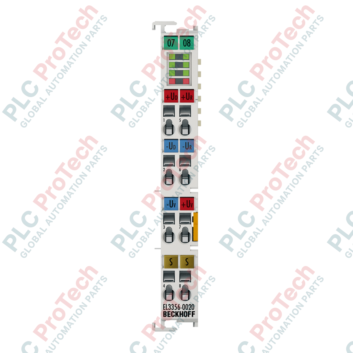
Designed specifically for high-accuracy gravimetric and force monitoring applications, the Beckhoff EL3356-0020 EtherCAT Terminal processes differential signals from full-bridge strain gauges with exceptional speed and precision. This terminal interfaces directly with resistor bridges to deliver reliable, factory-calibrated measurements in industrial process environments.
Key Features
- Direct interface for one resistor bridge in full-bridge technology.
- High-resolution 24-bit analog-to-digital conversion with 32-bit data presentation options.
- Factory calibration certificate stored internally for guaranteed accuracy.
- Supports Distributed Clocks (DC) for precise temporal synchronization across the EtherCAT network.
- Integrated dynamic filters, quadruple averager, and self-calibration routines.
Industrial Applications
- High-precision industrial platform scales and vessel weighing.
- Material testing machines and tensile strength evaluation systems.
- Silo and hopper level measurements with dynamic load distribution.
- Torque and force monitoring on rotating equipment.
Technical Specifications
| Parameter |
Specification Value |
| Manufacturer |
Beckhoff |
| Model Number |
EL3356-0020 |
| Product Type |
EtherCAT Terminal |
| Number of Inputs |
2, for 1 full-bridge resistor bridge |
| Technology Type |
Resistor bridge, strain gauge |
| Signal Type |
Differential |
| Distributed Clocks |
Yes |
| Measuring Range UD |
Max. -25 to +25 mV rated voltage |
| Measuring Range UREF |
Max. -12 to +12 V rated voltage |
| Internal Resistance |
> 200 kOhm (UREF), > 1 MOhm (UD) |
| Input Filter Limit |
10 kHz low pass (-3 dB) |
| Conversion Time |
0.1 to 250 ms (configurable) |
| Resolution |
24 bit (32 bit presentation) |
| Measurement Error |
< +/-0.01 % of calculated load value |
| E-bus Current Draw |
Typ. 280 mA |
| Calibration Type |
Factory calibrated (with certificate) |
| Operating Temperature |
0 to +55 degC |
| Dimensions (W x H x D) |
12 mm x 100 mm x 68 mm |
| Connection Technology |
Spring-actuated cage clamp |
| Wire Cross Section |
Solid/Stranded: 0.08 - 2.5 mm2 (AWG 28 - 14) |
| Shipping Weight |
2.0 kg |
Alternative Models & Compatibility
Comparing the EL3356-0020 to standard EL3356 terminals, the primary differentiator is the included factory calibration certificate stored directly within the terminal's internal non-volatile memory. To maintain compatibility with TwinCAT projects, ensure the corresponding EtherCAT XML Device Description (ESI) file matches this precise hardware revision to prevent E-bus initialization failures.
Application Pitfalls & Engineering Notes
When deploying inside high-density control panels, thermal fluctuations can degrade calibration accuracy. While the active self-calibration routine corrects for gain and offset drift, mounting the terminal away from high-heat components like variable frequency drives is recommended. Additionally, aggressive setting of dynamic filters (CoE 0x8000) may introduce signal delays that can affect high-speed check-weighing applications.
Commissioning & Wiring Tips
Shielding is critical when dealing with microvolt-level differential signals (UD). Run strain gauge cabling through dedicated conduits and terminate the overall shield directly to the grounded DIN rail via low-impedance grounding clamps. Ensure CoE parameters (such as the notch filter for 50 Hz/60 Hz noise rejection) are aligned with your localized grid frequency to maximize signal stability.
Installation Guidelines
CRITICAL WARNING: ELECTRICAL HAZARD
Ensure the main power supply and E-bus system are entirely de-energized before mounting, wiring, or removing this terminal. Failure to do so can result in electrical shock, transient surges on the bus, or permanent damage to the high-precision differential circuit of the measuring module.
1
Position the terminal on the standard 35 mm DIN rail (conforming to EN 60715) and slide it until the locking clip securely snaps into place.
2
Ensure reliable grounding of the DIN rail to establish a noise-free return path for the high-precision analog signals.
3
Strip wires to the recommended length of 8 to 9 mm. Insert a flathead screwdriver into the spring actuation slot to open the cage clamp, insert the wire, and release the screwdriver.
4
Configure the TwinCAT System Manager to recognize the new device, and verify calibration parameter integration via CoE online indices.