


Implementing 3-Switch XOR Ladder Logic with Internal Bit
Implement a 3-SPST switch XOR light circuit in LogixPro or RSLogix 500 using an internal relay bit. Includes truth tables, boolean equations, and verified.

Designed for noise-immune distributed industrial automation, the Beckhoff IP2020-B200 establishes robust control node links through a high-speed optical fiber interface. Operating as a decentralized Fieldbus Box, this module integrates seamlessly into Lightbus ring topologies to offer rapid data transmission speeds of 2.5 Mbaud over optical fiber lines. Its design provides native galvanic isolation and absolute immunity to electromagnetic interference (EMI), making it optimal for heavy-duty manufacturing zones. The module utilizes standardized M8 connection interfaces for control power routing and features specialized fiber-optic sockets configured for direct-plug compatibility.
| Parameter | Specification Value |
|---|---|
| Manufacturer | Beckhoff |
| Model Designation | IP2020-B200 |
| Bus Interface | 2 x fiber-optic socket for plug ZS1020-0010 |
| Data Transfer Rate | 2.5 Mbaud |
| Control Supply Voltage | 24 V DC (-15% / +20%) |
| Power Feed Connector | 1 x M8 male socket, 4-pin |
| Downstream Power Connector | 1 x M8 female socket, 4-pin |
| Electrical Isolation | Control voltage to fieldbus: Yes |
| Operating Temperature | 0 degC to 55 degC |
| Storage Temperature | -25 degC to 85 degC |
| Ingress Protection Rating | IP65 / IP66 / IP67 (conforms to EN 60529) |
| Vibration Resistance | Conforms to EN 60068-2-6 |
| Shock Resistance | Conforms to EN 60068-2-27 |
| Standards & Approvals | CE, UL |
| Net Weight | Approx. 250 g |
| Shipping Weight (Calculated) | 0.55 kg (including packaging material) |
| M8 Terminal Pin | Circuit Assignment | Functional Description |
|---|---|---|
| Pin 1 | +24 V DC Us | Control supply voltage for internal electronics |
| Pin 2 | +24 V DC Up | Auxiliary/load supply voltage for sensors/actuators |
| Pin 3 | GND Us | Reference ground for control electronics |
| Pin 4 | GND Up | Reference ground for sensor/actuator power circuits |
The IP2020-B200 relies on the standard Beckhoff Lightbus protocol (II2001 or FC2001 PCI cards). If migrating to EtherCAT-based infrastructure, consider transitioning to the EP-series Fieldbus Boxes (e.g., EP1111 or EP2028-0002). For maintenance of older optical rings, keep spare ZS1020-0010 plastic optical fiber plugs on hand, as connection alignment is critical to maintaining signal budget across consecutive nodes.
Plastic optical fibers (POF) must be cut perfectly perpendicular using a dedicated optical fiber cutter (such as Beckhoff ZS1023-0003). Ragged or angled cuts lead to high optical attenuation, triggering intermitted packet drops and system fault codes on the master controller. Maintain a minimum bend radius of 25 mm for the optical fiber to avoid permanent stress damage to the physical core.
When configuring node addresses via KS2000, ensure your PC-to-node interface baud rate is set to match the hardware default. When checking the optical power level budget, use the diagnostic register status flags inside the PLC control word to verify the optical link quality before putting the system into high-demand operation.
Mount the IP2020-B200 securely to a flat, rigid panel surface or machine frame using M4 industrial mounting bolts. Do not apply mechanical tension to the housing.
Insert the fiber-optic plugs (ZS1020-0010) into the dedicated optical ports. Ensure they seat firmly and the retention sleeve clicks or secures tightly.
Connect the 4-pin M8 auxiliary power cables to the male input port. Torque the M8 threaded connector ring to 0.4 Nm to guarantee the IP67 moisture seal.
If running downstream modules, extend power out of the female M8 port using industrial shielded cabling. Seal any unused ports with protective IP67 plastic caps.
Global Express Shipping
Returns & Warranty


Manufacturer: BECKHOFF
Product No.: IP2020-B200
Country of origin:Germany
Product Type: Fieldbus Box Modules
Payment: T/T, Western Union
Weight: 500g
Shipping port: Xiamen
Warranty: 12 months
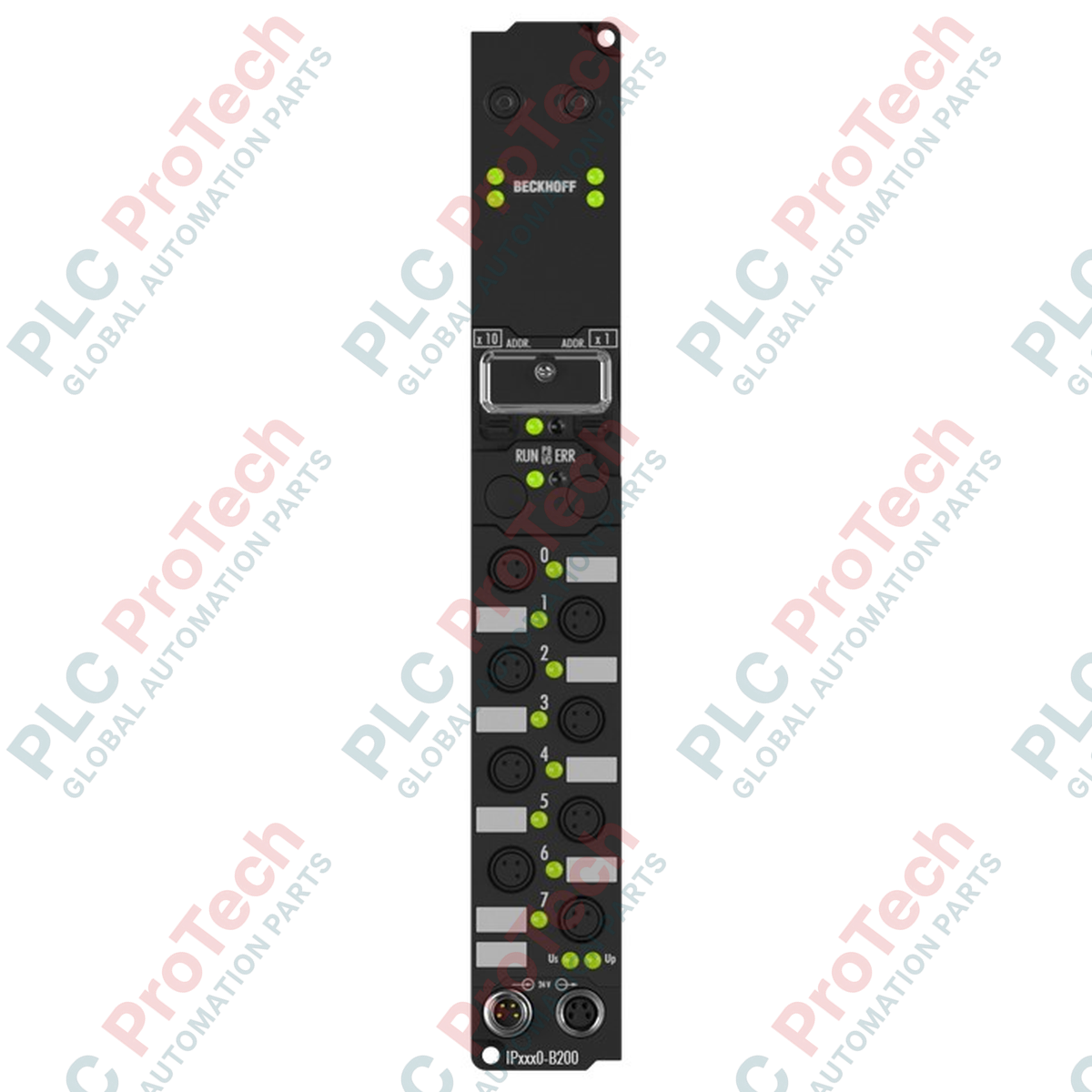
Designed for noise-immune distributed industrial automation, the Beckhoff IP2020-B200 establishes robust control node links through a high-speed optical fiber interface. Operating as a decentralized Fieldbus Box, this module integrates seamlessly into Lightbus ring topologies to offer rapid data transmission speeds of 2.5 Mbaud over optical fiber lines. Its design provides native galvanic isolation and absolute immunity to electromagnetic interference (EMI), making it optimal for heavy-duty manufacturing zones. The module utilizes standardized M8 connection interfaces for control power routing and features specialized fiber-optic sockets configured for direct-plug compatibility.
| Parameter | Specification Value |
|---|---|
| Manufacturer | Beckhoff |
| Model Designation | IP2020-B200 |
| Bus Interface | 2 x fiber-optic socket for plug ZS1020-0010 |
| Data Transfer Rate | 2.5 Mbaud |
| Control Supply Voltage | 24 V DC (-15% / +20%) |
| Power Feed Connector | 1 x M8 male socket, 4-pin |
| Downstream Power Connector | 1 x M8 female socket, 4-pin |
| Electrical Isolation | Control voltage to fieldbus: Yes |
| Operating Temperature | 0 degC to 55 degC |
| Storage Temperature | -25 degC to 85 degC |
| Ingress Protection Rating | IP65 / IP66 / IP67 (conforms to EN 60529) |
| Vibration Resistance | Conforms to EN 60068-2-6 |
| Shock Resistance | Conforms to EN 60068-2-27 |
| Standards & Approvals | CE, UL |
| Net Weight | Approx. 250 g |
| Shipping Weight (Calculated) | 0.55 kg (including packaging material) |
| M8 Terminal Pin | Circuit Assignment | Functional Description |
|---|---|---|
| Pin 1 | +24 V DC Us | Control supply voltage for internal electronics |
| Pin 2 | +24 V DC Up | Auxiliary/load supply voltage for sensors/actuators |
| Pin 3 | GND Us | Reference ground for control electronics |
| Pin 4 | GND Up | Reference ground for sensor/actuator power circuits |
The IP2020-B200 relies on the standard Beckhoff Lightbus protocol (II2001 or FC2001 PCI cards). If migrating to EtherCAT-based infrastructure, consider transitioning to the EP-series Fieldbus Boxes (e.g., EP1111 or EP2028-0002). For maintenance of older optical rings, keep spare ZS1020-0010 plastic optical fiber plugs on hand, as connection alignment is critical to maintaining signal budget across consecutive nodes.
Plastic optical fibers (POF) must be cut perfectly perpendicular using a dedicated optical fiber cutter (such as Beckhoff ZS1023-0003). Ragged or angled cuts lead to high optical attenuation, triggering intermitted packet drops and system fault codes on the master controller. Maintain a minimum bend radius of 25 mm for the optical fiber to avoid permanent stress damage to the physical core.
When configuring node addresses via KS2000, ensure your PC-to-node interface baud rate is set to match the hardware default. When checking the optical power level budget, use the diagnostic register status flags inside the PLC control word to verify the optical link quality before putting the system into high-demand operation.
Mount the IP2020-B200 securely to a flat, rigid panel surface or machine frame using M4 industrial mounting bolts. Do not apply mechanical tension to the housing.
Insert the fiber-optic plugs (ZS1020-0010) into the dedicated optical ports. Ensure they seat firmly and the retention sleeve clicks or secures tightly.
Connect the 4-pin M8 auxiliary power cables to the male input port. Torque the M8 threaded connector ring to 0.4 Nm to guarantee the IP67 moisture seal.
If running downstream modules, extend power out of the female M8 port using industrial shielded cabling. Seal any unused ports with protective IP67 plastic caps.
Global Express Shipping
Returns & Warranty
Orders are processed and delivered Monday-Friday (excluding public holidays).
For full eligibility, restocking fees, and international return details, please view our official Refund & Return Policy .
| Country of origin |
Germany
|

Implement a 3-SPST switch XOR light circuit in LogixPro or RSLogix 500 using an internal relay bit. Includes truth tables, boolean equations, and verified.

Integrate Allen-Bradley CompactLogix, Caterpillar ATS, and generators into DeltaV DCS over Modbus RTU. Covers ProSoft MVI69-MCM, Miille DIN266 gateways.

ONS instruction fires but the OTE coil never latches in Studio 5000 because the one-shot is only true for one scan. Use OTL/OTU or seal-in logic instead.

Configure Allen-Bradley Kinetix 5500 servo drives on EtherNet/IP. Covers CIP Sync, IEEE 1588 V2 timing, Stratix selection, DLR topology, and HMI.

A moving-average filter is the sliding-window smoother most instrument engineers drop into DCS and PLC analog paths. Here is how the window works, how N and sample time set lag, and when a...

On Frame 5–9 gas turbines, GE Mark VI and Mark VIe run control as function-block application software. This article maps process, protection, and sequencing functions—and what Toolbox ST access...