


Implementing 3-Switch XOR Ladder Logic with Internal Bit
Implement a 3-SPST switch XOR light circuit in LogixPro or RSLogix 500 using an internal relay bit. Includes truth tables, boolean equations, and verified.

Handling decentralized digital signals within RS485 fieldbus architectures is the primary role of the BECKHOFF IP2300-B800, a ruggedized fieldbus module engineered for direct machine mounting. This compact module integrates both digital inputs and digital outputs, allowing for high-density local I/O handling without the need for an electrical control cabinet. Featuring built-in RS485 communication, the device interfaces seamlessly with industrial host controllers, processing field signals with low latency. Its physical construction relies on robust M8 connection sockets, providing robust environmental resistance and secure locking mechanisms for industrial environments.
| Parameter | Specification Value |
|---|---|
| Manufacturer | BECKHOFF |
| Model Number | IP2300-B800 |
| Device Type | Fieldbus Box (Decentralized I/O) |
| Communication Interface | RS485 |
| Digital Inputs | 4 channels (24 V DC) |
| Input Filter Time | 3 ms |
| Digital Outputs | 4 channels (24 V DC) |
| Output Current Capacity | 0.5 A per channel |
| Connection Sockets | M8 round connectors (diameter 8 mm) |
| Nominal Supply Voltage | 24 V DC (-15% / +20%) |
| Operating Temperature | 0 to +55 degC |
| Storage Temperature | -25 to +85 degC |
| Ingress Protection Rating | IP67 (when all connections are mated or sealed) |
| Shipping Weight (Calculated) | 2.0 kg |
| Package Dimensions (Calculated) | 180 x 100 x 60 mm |
This RS485-configured unit provides physical serial bus integration. When transitioning from older field networks or migrating to Ethernet-based architectures, note that this module cannot be converted directly to EtherCAT (such as EP series) without changing the network coupler. Ensure your master controller supports standard Modbus RTU or Beckhoff standard serial protocol frames before finalizing integration.
While the housing boasts an IP67 protection rating, thermal behavior must be managed. In tightly enclosed panels or high-temperature ambient zones near motors, continuous 0.5 A loads across all four output channels simultaneously will generate localized internal heat. Ensure the module is mounted against a metal surface or frame that acts as a natural heat sink to avoid thermal throttling or output driver shutdown.
Always verify that the RS485 network segment is correctly terminated. The end of the physical bus line requires a 120-ohm termination resistor across the RX/TX differential lines. Keep the M8 signal cables separated from heavy motor power lines to minimize electromagnetic interference (EMI) on the serial communications line.
Isolate all electrical power sources before initiating physical mounting, wiring, or network configuration. Failing to fully discharge associated DC power networks can cause sudden electrical arcing, damaging internal solid-state output components and causing communication board failures.
Mount the Fieldbus Box directly to the machine frame or mounting plate using M4 screws, ensuring the surface is flat to prevent mechanical stress on the plastic enclosure.
Remove the protective cap on the rotary switch housing and configure the RS485 node ID according to your physical network plan before sealing the cap.
Connect the RS485 serial communication cables and secure the threaded M8 connections to guarantee IP67 sealing.
Wire the M8 input and output connections. Protect any unused M8 ports with IP67 screw plugs to prevent moisture ingress.
Connect the auxiliary 24 V DC power feed, verify that the diagnostic LEDs illuminate correctly, and execute a network scan from the host controller.
Global Express Shipping
Returns & Warranty


Manufacturer: BECKHOFF
Product No.: IP2300-B800
Country of origin:Germany
Product Type: Fieldbus Box Modules
Payment: T/T, Western Union
Weight: 2000g
Dimensions: 180 x 100 x 60 mm
Shipping port: Xiamen
Warranty: 12 months
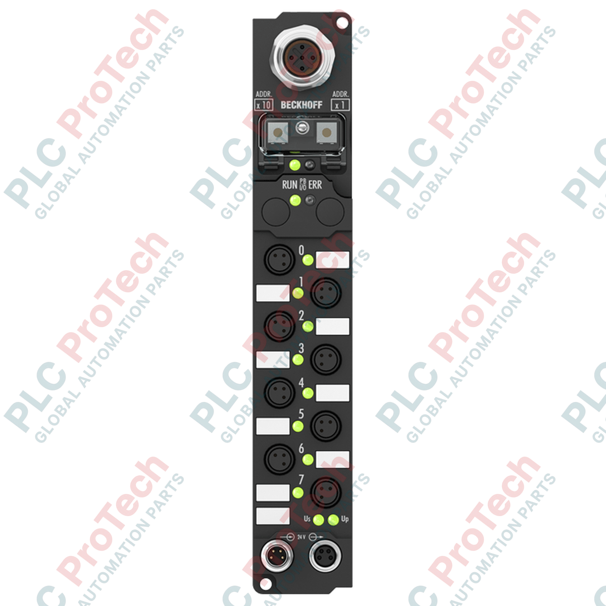
Handling decentralized digital signals within RS485 fieldbus architectures is the primary role of the BECKHOFF IP2300-B800, a ruggedized fieldbus module engineered for direct machine mounting. This compact module integrates both digital inputs and digital outputs, allowing for high-density local I/O handling without the need for an electrical control cabinet. Featuring built-in RS485 communication, the device interfaces seamlessly with industrial host controllers, processing field signals with low latency. Its physical construction relies on robust M8 connection sockets, providing robust environmental resistance and secure locking mechanisms for industrial environments.
| Parameter | Specification Value |
|---|---|
| Manufacturer | BECKHOFF |
| Model Number | IP2300-B800 |
| Device Type | Fieldbus Box (Decentralized I/O) |
| Communication Interface | RS485 |
| Digital Inputs | 4 channels (24 V DC) |
| Input Filter Time | 3 ms |
| Digital Outputs | 4 channels (24 V DC) |
| Output Current Capacity | 0.5 A per channel |
| Connection Sockets | M8 round connectors (diameter 8 mm) |
| Nominal Supply Voltage | 24 V DC (-15% / +20%) |
| Operating Temperature | 0 to +55 degC |
| Storage Temperature | -25 to +85 degC |
| Ingress Protection Rating | IP67 (when all connections are mated or sealed) |
| Shipping Weight (Calculated) | 2.0 kg |
| Package Dimensions (Calculated) | 180 x 100 x 60 mm |
This RS485-configured unit provides physical serial bus integration. When transitioning from older field networks or migrating to Ethernet-based architectures, note that this module cannot be converted directly to EtherCAT (such as EP series) without changing the network coupler. Ensure your master controller supports standard Modbus RTU or Beckhoff standard serial protocol frames before finalizing integration.
While the housing boasts an IP67 protection rating, thermal behavior must be managed. In tightly enclosed panels or high-temperature ambient zones near motors, continuous 0.5 A loads across all four output channels simultaneously will generate localized internal heat. Ensure the module is mounted against a metal surface or frame that acts as a natural heat sink to avoid thermal throttling or output driver shutdown.
Always verify that the RS485 network segment is correctly terminated. The end of the physical bus line requires a 120-ohm termination resistor across the RX/TX differential lines. Keep the M8 signal cables separated from heavy motor power lines to minimize electromagnetic interference (EMI) on the serial communications line.
Isolate all electrical power sources before initiating physical mounting, wiring, or network configuration. Failing to fully discharge associated DC power networks can cause sudden electrical arcing, damaging internal solid-state output components and causing communication board failures.
Mount the Fieldbus Box directly to the machine frame or mounting plate using M4 screws, ensuring the surface is flat to prevent mechanical stress on the plastic enclosure.
Remove the protective cap on the rotary switch housing and configure the RS485 node ID according to your physical network plan before sealing the cap.
Connect the RS485 serial communication cables and secure the threaded M8 connections to guarantee IP67 sealing.
Wire the M8 input and output connections. Protect any unused M8 ports with IP67 screw plugs to prevent moisture ingress.
Connect the auxiliary 24 V DC power feed, verify that the diagnostic LEDs illuminate correctly, and execute a network scan from the host controller.
Global Express Shipping
Returns & Warranty
Orders are processed and delivered Monday-Friday (excluding public holidays).
For full eligibility, restocking fees, and international return details, please view our official Refund & Return Policy .
| Country of origin |
Germany
|

Implement a 3-SPST switch XOR light circuit in LogixPro or RSLogix 500 using an internal relay bit. Includes truth tables, boolean equations, and verified.

Integrate Allen-Bradley CompactLogix, Caterpillar ATS, and generators into DeltaV DCS over Modbus RTU. Covers ProSoft MVI69-MCM, Miille DIN266 gateways.

ONS instruction fires but the OTE coil never latches in Studio 5000 because the one-shot is only true for one scan. Use OTL/OTU or seal-in logic instead.

Configure Allen-Bradley Kinetix 5500 servo drives on EtherNet/IP. Covers CIP Sync, IEEE 1588 V2 timing, Stratix selection, DLR topology, and HMI.

A moving-average filter is the sliding-window smoother most instrument engineers drop into DCS and PLC analog paths. Here is how the window works, how N and sample time set lag, and when a...

On Frame 5–9 gas turbines, GE Mark VI and Mark VIe run control as function-block application software. This article maps process, protection, and sequencing functions—and what Toolbox ST access...