BECKHOFF

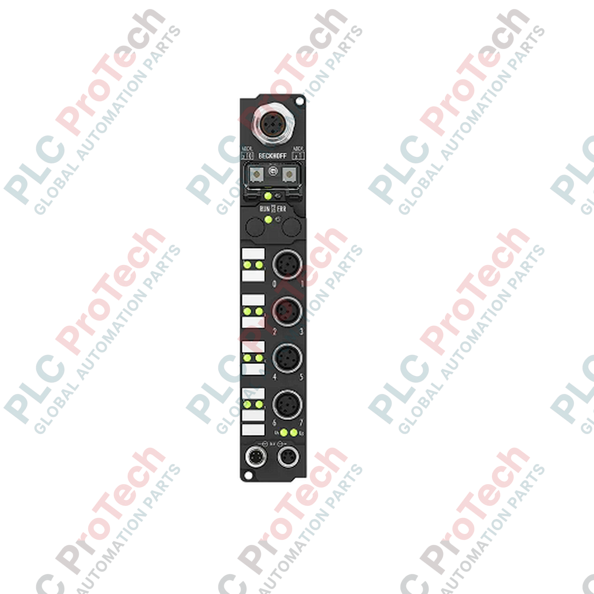
BECKHOFF IP2312-B730 Fieldbus Box

SKU IP2312-B730

In stock
  • 12-month warranty
  • Free returns within 30 days
  • Manufacturer: BECKHOFF
  • Product No.: IP2312-B730
  • Origin Germany
  • Product Type: Fieldbus Boxes
  • Payment: T/T, Western Union
  • Weight: 0.21 kg
  • Dimensions: 30 mm x 175 mm x 26.5 mm
  • Shipping port: Xiamen
  • Warranty: 12 months

Tags

Quantity

Product Description

Description

The BECKHOFF IP2312-B730 is a compact Fieldbus Box designed for direct machine mounting in demanding industrial environments. Operating as a decentralized I/O station, this module interfaces digital peripheral signals with serial networks utilizing the Modbus RTU/ASCII protocol. It features a combination of four digital inputs and four digital outputs, providing a highly integrated solution for localized sensor and actuator connection without the need for a protective control cabinet.

Constructed with a polyamide housing, the BECKHOFF IP2312-B730 achieves an IP65/66/67 protection rating, making it highly resistant to wet, dusty, or harsh operating conditions. Its design allows direct installation on machines using two simple mounting holes, reducing wiring complexity, minimizing cabinet space requirements, and simplifying field-level diagnostics.

Features

  • Modbus RTU/ASCII serial communication interface (RS485) supporting data transfer rates from 150 to 38,400 baud.
  • Integrated I/O configuration consisting of 4 digital inputs (24 V DC) and 4 digital outputs (24 V DC, 0.5 A).
  • High-density physical connections utilizing standard M12 screw-type connectors for secure field cabling.
  • Short-circuit proof digital outputs with individual channel protection capable of switching ohmic, inductive, and lamp loads.
  • Integrated address selection switches for quick network configuration and node addressing.
  • IP65/66/67-rated polyamide housing suitable for variable mounting orientations without a protective enclosure.

Applications

  • Decentralized machine-mount sensor and actuator integration in automated assembly lines.
  • Localized digital signal processing in conveyor systems and material handling machinery.
  • Direct-to-field fieldbus expansion in wet or dusty industrial manufacturing environments.
  • Modbus RTU serial network deployment where control cabinet space is limited or restricted.

Technical Specifications

General

Parameter Specification
Manufacturer BECKHOFF
Exact Model IP2312-B730
Product Type Fieldbus Box
Housing Material PA6 (polyamide)
Protection Rating IP65/66/67 (conforms to EN 60529)
Dimensions (W x H x D) 30 mm x 175 mm x 26.5 mm
Weight Approx. 210 g
Installation 2 x fixing holes (3.5 mm diameter for M3 screws)
Approvals and Markings CE, UL

Fieldbus and Configuration

Parameter Specification
Protocol Modbus RTU / Modbus ASCII
Data Transfer Medium Screened, twisted copper cable 2 x 0.25 mm² (RS485)
Bus Interface 1 x M12 socket, 5-pin, B-coded
Data Transfer Rates 150, 300, 600, 1200, 2400, 4800, 9600, 19,200, 38,400 baud
Configuration Method Address selection switch or KS2000 software
Bit Width in Process Image 4 inputs + 4 outputs

Digital Inputs

Parameter Specification
Number of Channels 4
Signal Voltage "0" -3 V to +5 V
Signal Voltage "1" 11 V to 30 V
Input Current 6 mA (EN 61131-2, Type 2)
Input Filter 0.2 ms
Sensor Supply From control voltage, max. 0.5 A total (short-circuit proof)

Digital Outputs

Parameter Specification
Number of Channels 4
Rated Load Voltage 24 V DC (-15% / +20%)
Max. Output Current 0.5 A per channel (individually short-circuit proof)
Short-Circuit Current Typical 1.5 A
Load Type Compatibility Ohmic, inductive, lamp load

Electrical Data

Parameter Specification
Control Voltage Supply 24 V DC (-15% / +20%)
Box Supply Current 45 mA + current consumption of sensors (max. 0.5 A)
Auxiliary Power Current Typical 20 mA per channel
Power Supply Connection (Feed) 1 x M8 male socket, 4-pin
Power Supply Connection (Downstream) 1 x M8 female socket, 4-pin
Electrical Isolation (Control Voltage/Fieldbus) Yes
Electrical Isolation (Channels/Control Voltage) No

Environmental and Mechanical

Parameter Specification
Operating Temperature 0 to +55 degC
Storage Temperature -25 to +85 degC
Vibration/Shock Resistance Conforms to EN 60068-2-6 / EN 60068-2-27
EMC Immunity/Emission Conforms to EN 61000-6-2 / EN 61000-6-4

Installation Guidelines

  1. De-energize the System: Ensure all power supplies (control voltage and auxiliary load supplies) are turned off before mounting, wiring, or configuring the device.
  2. Physical Mounting: Mount the module directly onto a flat surface or machine framework using the two 3.5 mm integrated mounting holes with suitable M3 screws. Ensure the mounting surface is clean and free of excessive vibration.
  3. Configure Addressing: Set the serial network address using the integrated rotary address selection switches or configure the device via the KS2000 software interface prior to securing the protective caps.
  4. Connect Fieldbus: Connect the RS485 Modbus serial line to the B-coded 5-pin M12 fieldbus interface socket.
  5. Wiring I/O and Power: Securely connect sensors and actuators to the M12 I/O channels. Connect the 24 V DC supply feed to the 4-pin M8 male connector. If daisy-chaining power, connect the downstream cable to the 4-pin M8 female socket.
  6. Seal Unused Ports: To maintain the IP65/66/67 environmental protection rating, fit protective caps on all unused M12 and M8 connector sockets.
Shipping & Returns

Global Express Shipping

  • Standard Delivery: 4–6 business days via DHL, FedEx, and UPS.
  • Express Dispatch: Same-day dispatch for in-stock orders placed before 2:00 PM (GMT+8).
  • Worldwide Coverage: Serving over 150 countries.

Returns & Warranty

  • 30-Day Guarantee: Returns accepted for in-stock products in original, factory-sealed packaging.
  • 12-Month Warranty: Every industrial component is backed by our technical warranty.
FAQ
What protocol does the BECKHOFF IP2312-B730 Fieldbus Box use?
The BECKHOFF IP2312-B730 uses the Modbus RTU/ASCII serial protocol over an RS485 physical interface, supporting adjustable baud rates from 150 to 38,400 baud.
What is the physical connection configuration of the BECKHOFF IP2312-B730?
The BECKHOFF IP2312-B730 features four digital inputs and four digital outputs utilizing standard M12 screw-type connections, while serial fieldbus communication is handled by a B-coded 5-pin M12 socket.
Does the BECKHOFF IP2312-B730 require a protective control cabinet?
No, the BECKHOFF IP2312-B730 is designed for direct machine installation. Its rugged polyamide housing provides an IP65/66/67 protection rating, making it resistant to dust, moisture, and spray water without needing an enclosure.
How are the inputs and outputs powered on the BECKHOFF IP2312-B730?
The BECKHOFF IP2312-B730 is supplied with 24 V DC control voltage through a 4-pin M8 male connector. The sensor supply is drawn from this control voltage up to a maximum of 0.5 A in total. Auxiliary load voltage is wired using the downstream M8 female connector for daisy-chain configurations.
Is there electrical isolation between the channels and control logic on the BECKHOFF IP2312-B730?
The BECKHOFF IP2312-B730 features complete electrical isolation between the control voltage/internal electronics and the serial fieldbus. However, there is no electrical isolation between the individual digital I/O channels themselves or between the channels and the internal control voltage supply.
Reviews

IP2312-B730

Stock & lead time on request

Call
1 of 1

BECKHOFF IP2312-B730 Fieldbus Box

Only 10 item(s) left in stock
  • Manufacturer: BECKHOFF

  • Product No.: IP2312-B730

  • Country of origin:Germany

  • Product Type: Fieldbus Boxes

  • Payment: T/T, Western Union

  • Weight: 210g

  • Dimensions: 30 mm x 175 mm x 26.5 mm

  • Shipping port: Xiamen

  • Warranty: 12 months

Quantity
View full details

Description

The BECKHOFF IP2312-B730 is a compact Fieldbus Box designed for direct machine mounting in demanding industrial environments. Operating as a decentralized I/O station, this module interfaces digital peripheral signals with serial networks utilizing the Modbus RTU/ASCII protocol. It features a combination of four digital inputs and four digital outputs, providing a highly integrated solution for localized sensor and actuator connection without the need for a protective control cabinet.

Constructed with a polyamide housing, the BECKHOFF IP2312-B730 achieves an IP65/66/67 protection rating, making it highly resistant to wet, dusty, or harsh operating conditions. Its design allows direct installation on machines using two simple mounting holes, reducing wiring complexity, minimizing cabinet space requirements, and simplifying field-level diagnostics.

Features

  • Modbus RTU/ASCII serial communication interface (RS485) supporting data transfer rates from 150 to 38,400 baud.
  • Integrated I/O configuration consisting of 4 digital inputs (24 V DC) and 4 digital outputs (24 V DC, 0.5 A).
  • High-density physical connections utilizing standard M12 screw-type connectors for secure field cabling.
  • Short-circuit proof digital outputs with individual channel protection capable of switching ohmic, inductive, and lamp loads.
  • Integrated address selection switches for quick network configuration and node addressing.
  • IP65/66/67-rated polyamide housing suitable for variable mounting orientations without a protective enclosure.

Applications

  • Decentralized machine-mount sensor and actuator integration in automated assembly lines.
  • Localized digital signal processing in conveyor systems and material handling machinery.
  • Direct-to-field fieldbus expansion in wet or dusty industrial manufacturing environments.
  • Modbus RTU serial network deployment where control cabinet space is limited or restricted.

Technical Specifications

General

Parameter Specification
Manufacturer BECKHOFF
Exact Model IP2312-B730
Product Type Fieldbus Box
Housing Material PA6 (polyamide)
Protection Rating IP65/66/67 (conforms to EN 60529)
Dimensions (W x H x D) 30 mm x 175 mm x 26.5 mm
Weight Approx. 210 g
Installation 2 x fixing holes (3.5 mm diameter for M3 screws)
Approvals and Markings CE, UL

Fieldbus and Configuration

Parameter Specification
Protocol Modbus RTU / Modbus ASCII
Data Transfer Medium Screened, twisted copper cable 2 x 0.25 mm² (RS485)
Bus Interface 1 x M12 socket, 5-pin, B-coded
Data Transfer Rates 150, 300, 600, 1200, 2400, 4800, 9600, 19,200, 38,400 baud
Configuration Method Address selection switch or KS2000 software
Bit Width in Process Image 4 inputs + 4 outputs

Digital Inputs

Parameter Specification
Number of Channels 4
Signal Voltage "0" -3 V to +5 V
Signal Voltage "1" 11 V to 30 V
Input Current 6 mA (EN 61131-2, Type 2)
Input Filter 0.2 ms
Sensor Supply From control voltage, max. 0.5 A total (short-circuit proof)

Digital Outputs

Parameter Specification
Number of Channels 4
Rated Load Voltage 24 V DC (-15% / +20%)
Max. Output Current 0.5 A per channel (individually short-circuit proof)
Short-Circuit Current Typical 1.5 A
Load Type Compatibility Ohmic, inductive, lamp load

Electrical Data

Parameter Specification
Control Voltage Supply 24 V DC (-15% / +20%)
Box Supply Current 45 mA + current consumption of sensors (max. 0.5 A)
Auxiliary Power Current Typical 20 mA per channel
Power Supply Connection (Feed) 1 x M8 male socket, 4-pin
Power Supply Connection (Downstream) 1 x M8 female socket, 4-pin
Electrical Isolation (Control Voltage/Fieldbus) Yes
Electrical Isolation (Channels/Control Voltage) No

Environmental and Mechanical

Parameter Specification
Operating Temperature 0 to +55 degC
Storage Temperature -25 to +85 degC
Vibration/Shock Resistance Conforms to EN 60068-2-6 / EN 60068-2-27
EMC Immunity/Emission Conforms to EN 61000-6-2 / EN 61000-6-4

Installation Guidelines

  1. De-energize the System: Ensure all power supplies (control voltage and auxiliary load supplies) are turned off before mounting, wiring, or configuring the device.
  2. Physical Mounting: Mount the module directly onto a flat surface or machine framework using the two 3.5 mm integrated mounting holes with suitable M3 screws. Ensure the mounting surface is clean and free of excessive vibration.
  3. Configure Addressing: Set the serial network address using the integrated rotary address selection switches or configure the device via the KS2000 software interface prior to securing the protective caps.
  4. Connect Fieldbus: Connect the RS485 Modbus serial line to the B-coded 5-pin M12 fieldbus interface socket.
  5. Wiring I/O and Power: Securely connect sensors and actuators to the M12 I/O channels. Connect the 24 V DC supply feed to the 4-pin M8 male connector. If daisy-chaining power, connect the downstream cable to the 4-pin M8 female socket.
  6. Seal Unused Ports: To maintain the IP65/66/67 environmental protection rating, fit protective caps on all unused M12 and M8 connector sockets.
Loading product navigation…

What protocol does the BECKHOFF IP2312-B730 Fieldbus Box use?

The BECKHOFF IP2312-B730 uses the Modbus RTU/ASCII serial protocol over an RS485 physical interface, supporting adjustable baud rates from 150 to 38,400 baud.

What is the physical connection configuration of the BECKHOFF IP2312-B730?

The BECKHOFF IP2312-B730 features four digital inputs and four digital outputs utilizing standard M12 screw-type connections, while serial fieldbus communication is handled by a B-coded 5-pin M12 socket.

Does the BECKHOFF IP2312-B730 require a protective control cabinet?

No, the BECKHOFF IP2312-B730 is designed for direct machine installation. Its rugged polyamide housing provides an IP65/66/67 protection rating, making it resistant to dust, moisture, and spray water without needing an enclosure.

How are the inputs and outputs powered on the BECKHOFF IP2312-B730?

The BECKHOFF IP2312-B730 is supplied with 24 V DC control voltage through a 4-pin M8 male connector. The sensor supply is drawn from this control voltage up to a maximum of 0.5 A in total. Auxiliary load voltage is wired using the downstream M8 female connector for daisy-chain configurations.

Is there electrical isolation between the channels and control logic on the BECKHOFF IP2312-B730?

The BECKHOFF IP2312-B730 features complete electrical isolation between the control voltage/internal electronics and the serial fieldbus. However, there is no electrical isolation between the individual digital I/O channels themselves or between the channels and the internal control voltage supply.

Global Express Shipping

  • Standard Delivery: 4-6 Business Days via DHL, FedEx, and UPS.
  • Express Dispatch: Same-day dispatch for in-stock orders placed before 2:00 PM (GMT+8).
  • Worldwide Coverage: Serving over 150 countries, including rapid delivery to Saudi Arabia and UAE.

Returns & Warranty

  • 30-Day Guarantee: Returns accepted for in-stock products in original, factory-sealed packaging.
  • 12-Month Warranty: Every industrial component is backed by our professional technical warranty.

Orders are processed and delivered Monday-Friday (excluding public holidays).


For full eligibility, restocking fees, and international return details, please view our official Refund & Return Policy .

TECHNICAL SPECIFICATIONS

Country of origin
Germany

Technical knowledge

Implementing 3-Switch XOR Ladder Logic with Internal Bit

Implement a 3-SPST switch XOR light circuit in LogixPro or RSLogix 500 using an internal relay bit. Includes truth tables, boolean equations, and verified.

Building a Modbus RTU Network with CompactLogix and DeltaV

Integrate Allen-Bradley CompactLogix, Caterpillar ATS, and generators into DeltaV DCS over Modbus RTU. Covers ProSoft MVI69-MCM, Miille DIN266 gateways.

ONS Instruction Not Energizing OTE in Studio 5000 Ladder Logic

ONS instruction fires but the OTE coil never latches in Studio 5000 because the one-shot is only true for one scan. Use OTL/OTU or seal-in logic instead.

Kinetix 5500 EtherNet/IP Network Switch Requirements and Topology

Configure Allen-Bradley Kinetix 5500 servo drives on EtherNet/IP. Covers CIP Sync, IEEE 1588 V2 timing, Stratix selection, DLR topology, and HMI.

Moving Average Filtering in DCS and PLC Analog Control

A moving-average filter is the sliding-window smoother most instrument engineers drop into DCS and PLC analog paths. Here is how the window works, how N and sample time set lag, and when a...

GE Mark VI Function Blocks for Gas Turbine Control Logic

On Frame 5–9 gas turbines, GE Mark VI and Mark VIe run control as function-block application software. This article maps process, protection, and sequencing functions—and what Toolbox ST access...