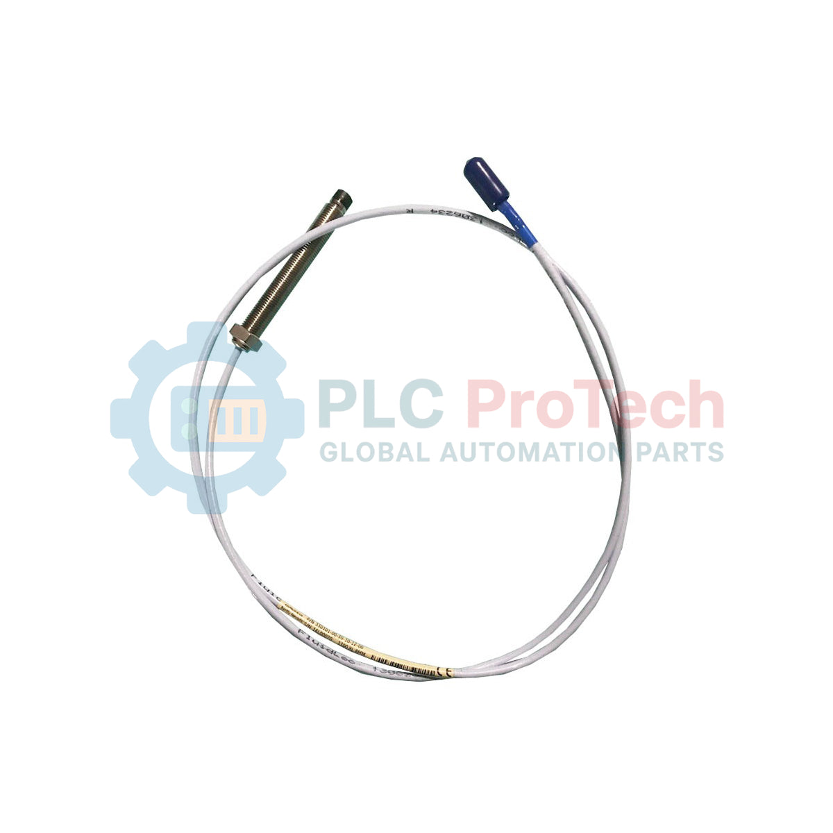
Description
Designed for high-precision machinery vibration and shaft position monitoring, the Bently Nevada 330101-00-61-20-02-CN serves as a critical sensing component within the 3300 XL 8 mm Proximity Transducer System. By establishing a reliable radio-frequency (RF) field, this non-contacting sensor translates the physical distance between the probe tip and the observed target into an electrical signal. Built to endure challenging physical environments, this model features a Polyphenylene sulfide (PPS) probe tip and a durable AISI 303/304 stainless steel case, making it ideal for continuous turbomachinery protection and diagnostic services.
Features
-
High-Durability Tip: Constructed from polyphenylene sulfide (PPS) to resist chemical exposure, moisture absorption, and thermal degradation in aggressive industrial fluids.
-
Rugged Case Material: Enclosed in a corrosion-resistant AISI 303 or 304 stainless steel (SST) housing, providing structural integrity in high-vibration applications.
-
ClickLoc Connection: Equipped with a miniature coaxial ClickLoc connector to resist physical loosening from rotational torque and field vibrations.
-
FEP Insulation: The 75-ohm triaxial probe cable is insulated with fluoroethylene propylene (FEP), offering excellent electrical isolation and chemical shielding.
-
Standard System Integration: Fully compatible with the 3300 XL system architecture for linear, highly stable output characteristics across the entire range.
Applications
- Steam and gas turbine shaft radial vibration and axial thrust position tracking.
- Centrifugal and axial compressor rotor dynamic monitoring and blade path assessments.
- Hydroelectric generator guide bearing radial movement tracking.
- Heavy industrial gearbox shaft centerline positioning and oil film thickness analysis.
- High-speed pump shaft deflection and mechanical seal monitoring.
Technical Specifications
| Parameter |
Specification |
| Manufacturer |
Bently Nevada |
| Part Number |
330101-00-61-20-02-CN |
| Product Series |
3300 XL 8 mm Proximity Transducer System |
| Unthreaded Length Option |
00 (0.0 inches / 0 mm) |
| Overall Case Length Option |
61 (6.1 inches) |
| Total Length Option |
20 (2.0 meters / 6.6 feet) |
| Connector and Cable-Type |
02 (Miniature coaxial ClickLoc connector, standard cable) |
| Agency Approval Option |
CN (Country-specific hazardous area/metrology approvals) |
| Probe Tip Material |
Polyphenylene sulfide (PPS) |
| Probe Case Material |
AISI 303 or AISI 304 Stainless Steel (SST) |
| Cable Style |
75-ohm triaxial, FEP insulated |
| Country of Origin |
United States |
| Net Weight |
0.323 kg (0.71 lbs) |
| Shipping Weight (Calculated) |
1.500 kg (3.31 lbs) |
Empirical Engineering Insights
Alternative Models & Compatibility
The 3300 XL 8 mm proximity probe is designed for seamless physical and electrical replacement of standard, non-XL 3300 8 mm probes. However, field engineers must note that while the probe is mechanically compatible, mixing XL and non-XL system components (such as combining a 3300 XL probe with a legacy 3300 Proximitor Sensor) can degrade the system's temperature stability and slightly alter the Scale Factor (normally 7.87 V/mm or 200 mV/mil). For critical TSI (Turbine Supervisory Instrumentation) loops, maintain matched 3300 XL hardware across the probe, extension cable, and Proximitor sensor.
Application Pitfalls & Engineering Notes
To prevent spatial signal distortion, ensure a minimum clearance of 15.2 mm (0.6 in) around the probe tip from any adjacent metallic objects. Mounting the probe tip too close to structural brackets or dynamic shaft collars will cause the RF field to couple with non-target metal, leading to false displacement readings. Additionally, ensure the FEP cable is not subjected to a bend radius smaller than 25.4 mm (1.0 in) during routing to prevent core-to-shield shorting and signal attenuation under thermal cycling.
Commissioning & Wiring Tips
When routing the probe cable through machine casings, always use dynamic conduit or protective sleeving to protect the FEP jacket from sharp metal edges and process fluids. Use a dedicated connector protector kit when snapping the ClickLoc coaxial connector together. Ensure the connection is completely free of moisture, oil, or thread sealant before mating, as any chemical contamination inside the connector will degrade the high-frequency impedance, resulting in intermitent "Sensor Limit" or "OK" circuit faults at the monitoring rack.
Installation Guidelines
CRITICAL WARNING: SAFETY FIRST
Prior to installing or adjusting any proximity probe, ensure the target machinery is completely de-energized, locked out, and tagged out. Verify that the monitoring system and local Proximitor loop power are fully disconnected to eliminate any spark hazards or risk of shock inside hazardous areas.
1
Mechanical Mounting: Thread the probe into the mounting bracket or sleeve. Check that the unthreaded length (0 mm for this model) aligns correctly with your bracket configuration to ensure complete mechanical support along the case.
2
Gap Calibration: Using a digital multimeter connected to the Proximitor sensor output, adjust the physical position of the probe until the DC voltage matches the specified target center gap voltage (typically -10.0 VDC for standard 3300 XL systems, which corresponds to the physical mid-point of the linear range).
3
Locknut Torquing: Tighten the probe locknut to the recommended OEM torque specifications to secure the probe case in position. Re-verify the DC gap voltage post-torquing to ensure the probe did not migrate during the tightening sequence.
4
Cable Routing & Mating: Join the ClickLoc miniature coaxial connector to the extension cable. Ensure the connection is secure, then route the triaxial cable back to the Proximitor enclosure through isolated conduits to block external electromagnetic noise.