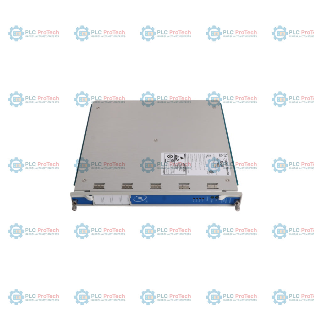
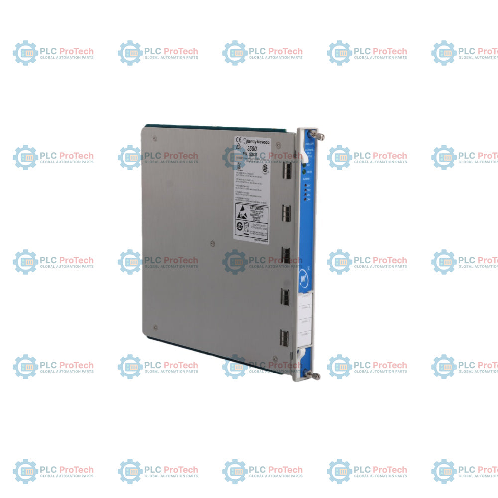
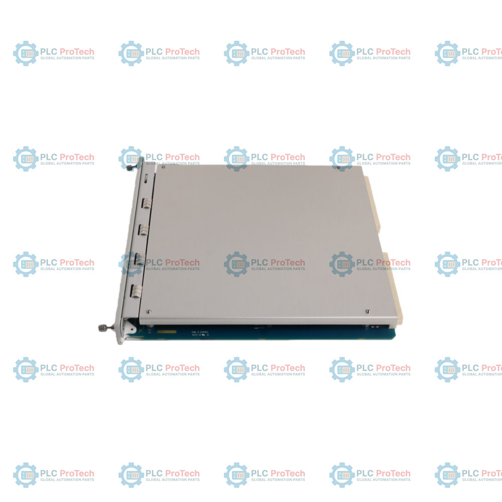
The 3500/32 is a full-height component designed for the Bently Nevada 3500 series machinery protection system, providing four fully programmable relay outputs. This module can be placed in any of the slots to the right of the Rack Interface Module to drive critical alarm and machinery shutdown logic. Each relay utilizes highly configurable Alarm Drive Logic, which can be custom programmed using AND and OR combinations of alerts and dangers from any monitor channel within the rack. This decentralized logic configuration operates via the 3500 Rack Configuration Software to execute protective actions instantly, independent of host software control.
The hardware employs a highly resilient relay setup consisting of two single-pole, double-throw (SPDT) relays arranged in a double-pole, double-throw (DPDT) configuration for each of its four channels. Every channel features switch-selectable operations for Normally De-energized or Normally Energized modes, enabling flexible adaptation to fail-safe industrial layouts. Built-in onboard LED indicators allow field operators to perform dynamic, at-a-glance status tracking of communication buses and individual relay alarm conditions.
Alarm Drive Logic programming supporting extensive combinations of AND/OR parameters across rack-wide inputs.
Dual SPDT relays connected in a robust DPDT physical layout for each independent channel.
Epoxy-sealed relay constructions integrated with standard 250 Vrms arc suppressors for sustained contact safety.
Onboard switch-selectable control allowing direct toggling between Normally Energized and Normally De-energized states.
Clear front-panel LED diagnostics indicating module OK, communication (TX/RX), and individual channel alarm status.
Applications
Automatic emergency trip logging and machinery shutdown loops on critical industrial turbomachinery.
Interlocking plant safety systems and visual/audible alarm annunciator drive networks.
Distributed voting logic configurations for balance-of-plant protection matrices across power generation and oil refineries.
Ordering Information
Detail
Product Ordering Reference
Main Model Designation
3500/32 (4-Channel Relay Module)
Output Module Option
-01 (4-Channel Relay I/O Module)
Agency Approval Option
-00 (None)
-01 (CSA / NRTL / C)
Technical Specifications
Parameter
Detail
Manufacturer
Bently Nevada (Baker Hughes)
Model Designation
3500/32
Product Type
4-Channel Relay Module
Power Consumption
6 watts typical
Relay Type Configuration
Two SPDT relays connected in a DPDT configuration per channel
Environmental Sealing
Epoxy-sealed
Arc Suppressor Rating
250 Vrms (installed as standard)
Contact Life Performance
100,000 cycles at 5 A, 24 Vdc or 120 Vac
Max Switched Voltage
dc: 30 Vdc / ac: 250 Vac
Max Switched Current
5 A
Minimum Switched Current
10 mA @ 5 Vdc
Switched Power Capacity
dc: 120 W / ac: 600 VA
Main Module Dimensions (H x W x D)
241 mm x 24.4 mm x 242 mm
Main Module Weight
0.7 kg
I/O Module Dimensions (H x W x D)
241 mm x 24.4 mm x 99.1 mm
I/O Module Weight
0.4 kg
Operating Temperature Bounds
-30 degC to +65 degC
Storage Temperature Bounds
-40 degC to +85 degC
Humidity Constraints
95%, non-condensing
Rack Space Requirement (Main)
1 full-height front slot
Rack Space Requirement (I/O)
1 full-height rear slot
Connections/Interfaces
Terminal Connection
Function Assignment
NC
Normally Closed contact connection point per relay channel
ARM
Armature / Common contact connection point per relay channel
NO
Normally Open contact connection point per relay channel
RELAY MODE (NDE/NE)
Hardware slide switches controlling individual channel energization states
Installation Guidelines
Module Placement: Slide the main card directly into any available full-height front slot to the right of the Rack Interface Module. Insert the corresponding I/O module into the matching rear chassis slot. Secure all faceplate screws.
Relay Mode Selection: Adjust the dedicated hardware switches on the I/O panel prior to module power-up to establish Normally De-energized (NDE) or Normally Energized (NE) operation based on loop design.
Wiring Configurations: Land all external device circuits onto the rear screw termination header block. Ensure proper landing for NC, ARM, and NO contact segments to prevent mechanical signaling errors.
Electrostatic Grounding: Utilize a single-use grounding wrist strap when unboxing or modifying the internal circuitry parameters to safeguard the board elements from electrostatic shock.
Compliance and Certifications
CE Mark Directives: Compliant with EMC Directive standards.
Radiated & Conducted Emissions: EN 55011, Class A.
Immunity & Susceptibility Standard: IEC 61000-6-2, including ESD (61000-4-2), Radiated (ENV 50140), Conducted (ENV 50141), EFT (EN 61000-4-4), Surge (EN 61000-4-5), and Magnetic Field (61000-4-8).
Hazardous Area Approvals: CSA/NRTL/C certified for Class I, Division 2, Groups A, B, C, D (T4 @Ta = -20 degC to +65 degC; Certification Number: CSA 150268-1002151).
FAQ
Can this relay module be utilized within Triple Modular Redundant configurations?
No. Triple Modular Redundant (TMR) applications require the specialized 3500/34 TMR Relay Module rather than the standard 3500/32 4-Channel Relay Module.
What configuration controls the baseline operational state of the relay contacts?
Each independent channel features physical switches on the hardware module that allow the selection between Normally De-energized and Normally Energized operations.
What built-in protection is provided to control contact degradation from electrical arcing?
Every channel on the module comes equipped with a 250 Vrms arc suppressor installed as standard equipment to mitigate damage from switching arcs.
A field replacement guide for GE Fanuc IC200MDL650 covering revision-dependent negative logic, four common groups, 24 VDC thresholds, input filtering, carrier checks and commissioning records.
A field-focused IC697CPX935 replacement guide covering fast memory, firmware-dependent serial behavior, rack power, cooling, I/O architecture and backup records.
A field-focused IC693DSM324 replacement guide covering Series 90-30 host checks, FSSB servo-chain records, 5 V power budget, firmware limits, follower control and commissioning.