Description
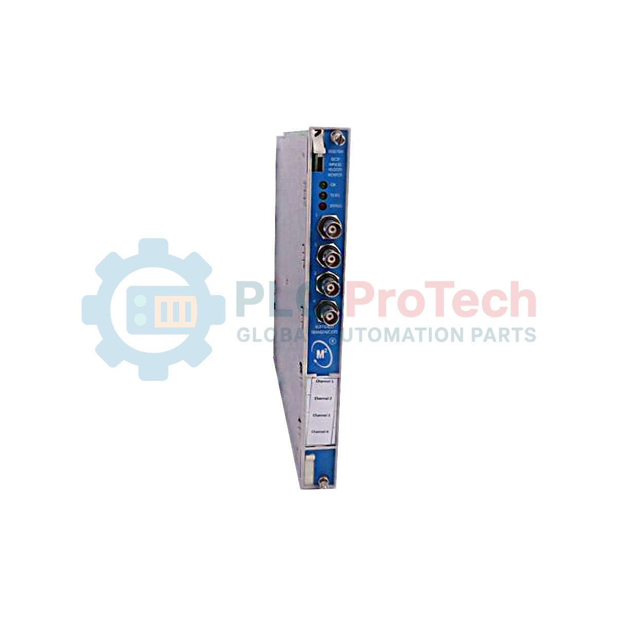
Designed for integration within the 3500 Machinery Protection System, the Bently Nevada 3500/61-05-00 serves as a specialized RTD/TC non-isolated input/output interface featuring internal safety barriers. This module functions alongside the 3500/61 Temperature Monitor to process and route temperature transducer signals directly from machinery components to external recording systems, strip charts, or process controllers.
The 3500/61-05-00 facilitates reliable signal transmission by providing conditioned recorder outputs that represent the measured values. By incorporating internal barriers, this hardware configuration provides an integrated solution for safeguarding field wiring connections in hazardous environments without requiring auxiliary external barrier systems.
Features
- Direct interface for Resistance Temperature Detectors (RTD) and Thermocouples (TC).
- Internal safety barriers designed to limit electrical energy in hazardous areas.
- Provides continuous, proportional analog recorder outputs for data logging and trend analysis.
- Non-isolated I/O configuration optimized for high-density, centralized rack installations.
- Compatible with standard 3500 Series monitoring racks and backplanes.
Applications
- Steam and gas turbine temperature monitoring.
- Large industrial motor and generator winding protection.
- Compressor and pump bearing temperature tracking.
- Petrochemical and oil refining process control interfaces.
Technical Specifications
Manufacturer
| Bently Nevada |
Part Number / Model
| 3500/61-05-00 |
Series
| 3500 Machinery Protection System |
I/O Module Type
| RTD/TC Non-isolated I/O Module with Internal Barriers |
Agency Approval Option
| None (Option 00) |
Country of Origin
| USA |
Weight
| 0.91 kg |
Installation Guidelines
- Ensure the 3500 system rack is completely powered down before installing or removing the I/O module.
- Insert the 3500/61-05-00 into the rear of the chassis, directly aligning it with the corresponding 3500/61 monitor card slot.
- Tighten the rear panel screws to secure the module and maintain proper chassis grounding connection.
- Verify loop impedance and barrier electrical limits prior to landing RTD or TC field wiring.
- Route low-voltage sensor cables away from high-power AC conductors to minimize electromagnetic interference.