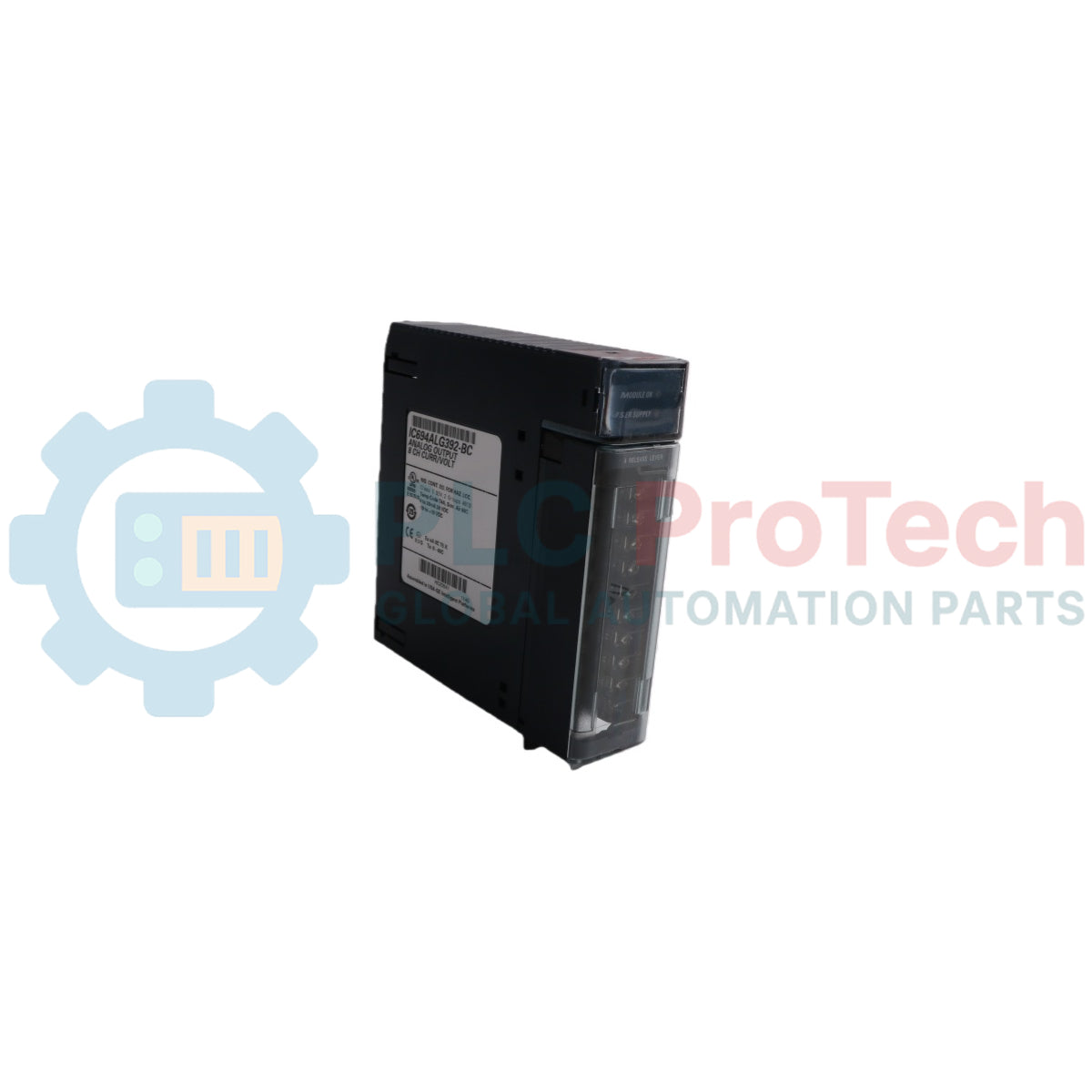
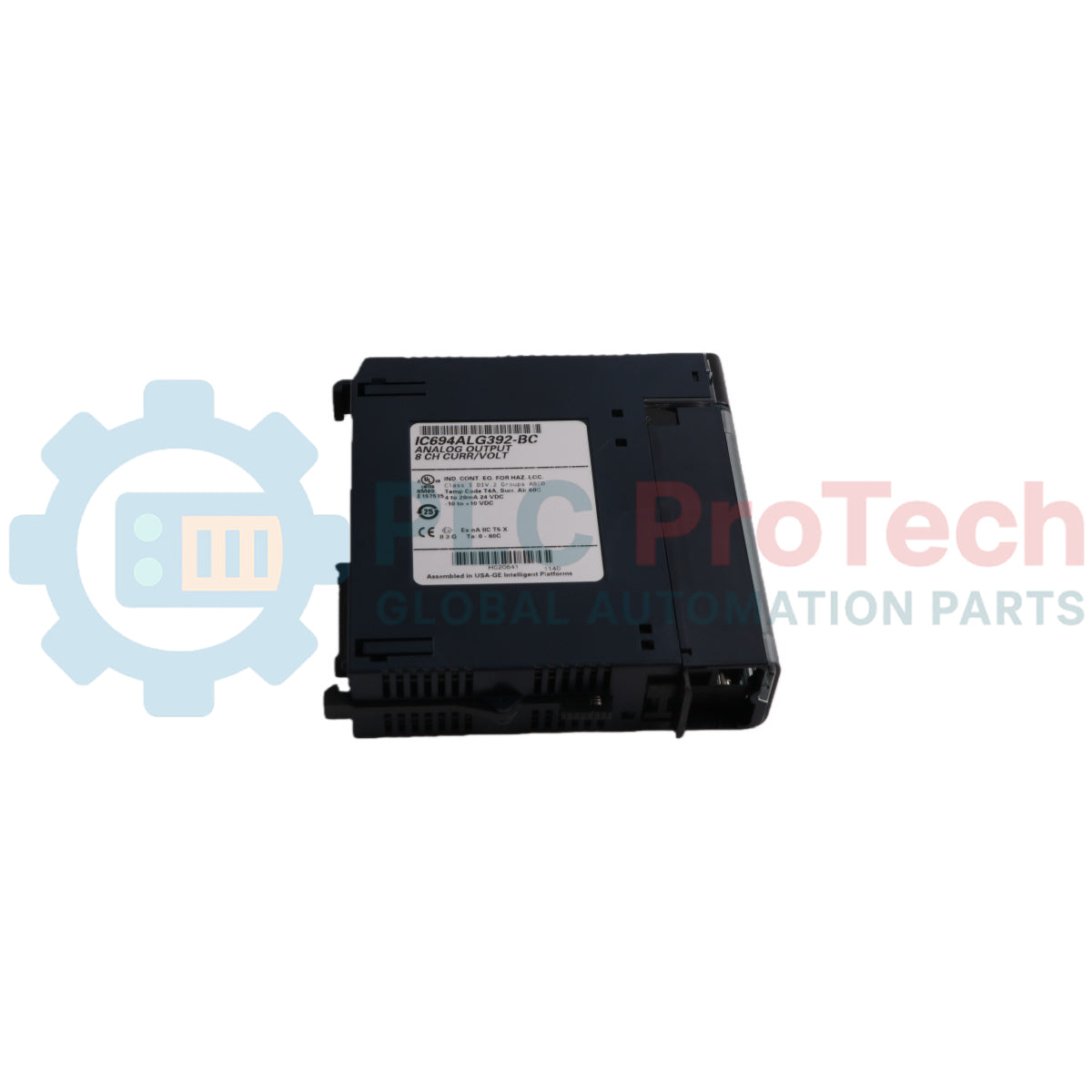
1 of 3

GE Fanuc IC694ALG392 PACSystems RX3i and Series 90-30 Analog Output Module

GE Fanuc IC694ALG392 PACSystems RX3i and Series 90-30 Analog Output Module

Only 2 item(s) left in stock
  • Manufacturer: General Electric

  • Product No.: IC694ALG392

  • Country of origin:United States

  • Product Type: Analog Output Module

  • Barcode: 8537101190

  • Payment: T/T, Western Union

  • Weight: 900g

  • Dimensions: 20cm x 11.5cm x 5.7cm

  • Shipping port: Xiamen

  • Warranty: 12 months

Quantity
View full details

Description

The IC694ALG392 is an 8-channel analog output module designed for use with PACSystems RX3i and Series 90-30 PLC systems. It provides up to eight single-ended output channels with current loop outputs and/or voltage outputs. Each output channel can be independently set up using the configuration software for any of these ranges: 0 to +10 V (unipolar), -10 to +10 V (bipolar), 0 to 20 mA, and 4 to 20 mA.

Each channel of the IC694ALG392 is capable of converting 15 to 16 bits (depending on the range selected) of binary data to an analog output. All eight channels are updated approximately every 8 milliseconds, determined by the I/O scan time and application. In current modes, the module reports an Open Wire fault to the CPU for each channel. As long as external power is applied to the module, each output will maintain its last value or reset to zero, as configured, when system power is interrupted. This module can be installed in any I/O slot of an RX3i or Series 90-30 system.

Features

  • 1 to 8 selectable single-ended analog output channels.
  • Flexible software configuration for multiple current and voltage ranges.
  • High-resolution conversion (15 to 16 bits depending on the selected range).
  • Fast update rate of approximately 8 milliseconds for all eight channels.
  • Channel-specific Open Wire fault reporting to the CPU in current loop modes.
  • Configurable default behavior (maintain last value or reset to zero) upon system power interruption.
  • Dual LED diagnostics driven by the backplane power bus to indicate module state and user supply status.

Applications

  • Proportional control valves and industrial actuators.
  • Speed reference signaling for variable frequency drives (VFD).
  • Dynamic chart recorders and process data logging equipment.
  • Interface connections to remote instrumentation panels.
  • Industrial automated processes in standard and Class I, Division 2 environments.

Ordering Information

Model / Version Description
IC694ALG392-AA Initial product release for RX3i module series (Version 1.00).
IC694ALG392-BB RX3i module series revision; not compatible with a Series 90-30 Hand-held Programmer.
IC694ALG392-BC RX3i module series firmware version 1.01 release.
IC694ALG392-CD RX3i module series firmware version 1.60 release.
IC693ALG392-A Initial release for Series 90-30 module series (Version 1.00).
IC693ALG392-B Series 90-30 module series with CE certification (Version 1.00).
IC693ALG392-C Series 90-30 module series with ATEX approval for Group 2, category 3 applications (Version 1.00).
IC693ALG392-BD Series 90-30 module series with updated processor and D/A converter (Version 1.00).
IC693ALG392-BE Series 90-30 module series firmware version 1.01 release.
IC693ALG392-CF Series 90-30 module series firmware version 1.60 release.

Technical Specifications

Parameter Specification
Manufacturer GE Intelligent Platforms, Inc. 
Model IC694ALG392 
Number of Output Channels 1 to 8 selectable, single-ended 
Output Current Range 4 to 20 mA and 0 to 20 mA 
Output Voltage Range 0 to 10 V and -10 V to +10 V 
Calibration Factory calibrated to 0.625 uA for 0 to 20 mA; 0.5 uA for 4 to 20 mA; and 0.3125 mV for voltage (per count) 
Resolution (4 to 20 mA) 0.5 uA (1 LSB = 0.5 uA) 
Resolution (0 to 20 mA) 0.625 uA (1 LSB = 0.625 uA) 
Resolution (0 to 10 V) 0.3125 mV (1 LSB = 0.3125 mV) 
Resolution (-10 to +10 V) 0.3125 mV (1 LSB = 0.3125 mV) 
Update Rate 8 milliseconds (approximate, all eight channels). Determined by I/O scan time, application dependent. 
Absolute Accuracy (Current Mode) +/-0.1% of full scale @ 25 degC (77 degF), typical; +/-0.25% of full scale @ 25 degC (77 degF), maximum; +/-0.5% of full scale over operating temperature range (maximum) 
Absolute Accuracy (Voltage Mode) +/-0.25% of full scale @ 25 degC (77 degF), typical; +/-0.5% of full scale @ 25 degC (77 degF), maximum; +/-1.0% of full scale over operating temperature range (maximum) 
User Supply Voltage (Nominal) +24 VDC, from user supplied voltage source 
External Supply Voltage Range 20 VDC to 30 VDC 
Power Supply Rejection Ratio (Current) 5 uA/V (typical), 10 uA/V (maximum) 
Power Supply Rejection Ratio (Voltage) 25 mV/V (typical), 50 mV/V (maximum) 
External Power Supply Voltage Ripple 10% (maximum) 
Internal Supply Voltage +5 VDC from PLC backplane 
Maximum Compliance Voltage VUSER -3 V (minimum) to VUSER (maximum) 
User Load (Current Mode) 10 to 850 Ohms (minimum at VUSER = 20 V, maximum 1350 Ohms at VUSER = 30 V). (Load less than 800 Ohms is temperature dependent.) 
Output Load Capacitance (Current Mode) 2000 pF (maximum) 
Output Load Inductance (Current Mode) 1 H 
Output Loading (Voltage Mode) 5 mA (2 K Ohms minimum resistance) 
Output Load Capacitance (Voltage Mode) 1 uF maximum capacitance 
Isolation, Field to Backplane 250 VAC continuous; 1500 VDC for 1 minute (optical and to frame ground) 
Power Consumption (Internal) 110 mA from +5 VDC PLC backplane supply 
Power Consumption (External) 315 mA from +24 VDC user supply 

Connections and Interfaces

Terminal Signal Definition
1 User Supplied +24 VDC Input 
2 Channel 1 Voltage Output 
3 Channel 1 Current Output 
4 Channel 2 Voltage Output 
5 Channel 2 Current output 
6 Channel 3 Voltage Output 
7 Channel 3 Current output 
8 Channel 4 Voltage Output 
9 Channel 4 Current output 
10 Channel 5 Voltage Output 
11 Channel 5 Current output 
12 Channel 6 Voltage Output 
13 Channel 6 Current output 
14 Channel 7 Voltage Output 
15 Channel 7 Current output 
16 Channel 8 Voltage Output 
17 Channel 8 Current output 
18 Voltage Common 
19 Current Common/User +24 VDC Return 
20 Frame ground connection for cable shields 


Note: Each channel can be configured to operate as a voltage output or a current output - not both simultaneously.

Module Status Indicators

LED State Indicates
OK ON Module OK and configured 
OK Flashing Module OK but not configured 
OK OFF Module is defective or no +5V backplane power present 
USER OK ON External power supply present 
USER OK OFF No user power 

Installation Guidelines

  • External Power Connection: The module must receive its 24 VDC power from an external source connected directly to Terminal 1 and Terminal 19 of the module's terminal block.
  • Thermal Derating: For maximum performance and module life, the module should be operated at maximum load resistance to offload heat. Module thermal deratings depend on the voltage level and the mix of current and voltage outputs. For example, at VUSER = 30 V with 2 voltage channels (2 K Ohm loads) and 3 current channels (shorted loads), the maximum operating temperature is approximately 52.5 degC.
  • RF Susceptibility and Shielding: In order to meet the specified RF susceptibility levels, the system must be mounted in a metal enclosure when this module is present. In the presence of severe RF interference, accuracy may be degraded to +/-1% full scale (FS) for current outputs and +/-3% FS for voltage outputs.
  • Cable Grounding: Wire the cable shield ground directly to Terminal 20 (Frame Ground).
  • Hazardous Area Precautions: Suitable for use in Class I, Division 2, Groups A, B, C, and D or non-hazardous locations only.
  • Explosion Hazard Warnings: Turn off power before replacing or wiring modules when in hazardous locations. Do not disconnect equipment unless power has been switched off or the area is known to be non-hazardous. Component substitution may impair suitability for Class I, Division 

System Compatibility Requirements

  • Series 90-30 CPU Firmware: For Series 90-30 PLC CPU firmware versions 3.3 to 4.6, the module must be configured for 16 %I inputs, otherwise a Loss of Module Fault will occur. CPU firmware must be version 5.0 or later to configure the module for 8 %I inputs.
  • Hand-Held Programmer: Only Series 90-30 modules version C or earlier support the Series 90-30 Hand-held Programmer. Series 90-30 modules version BD or later and all versions of RX3i modules cannot be used with a Hand-held Programmer.

Compliance and Certifications

  • Class I, Division 2, Groups A, B, C, D Hazardous Locations 

Product Documentation

Technical Datasheet (PDF) Complete specifications and technical drawings.
Download Now

Can a single channel output both voltage and current simultaneously?

No. Each of the eight channels must be configured via software to function as either a voltage output or a current output, but cannot output both at the same time.

What happens to the analog outputs if the PLC backplane loses power?

If system power is lost but external +24 VDC remains applied to the terminal block, each channel will hold its last commanded value or reset to zero based on its configuration.

How does the module signal a field wiring loop failure to the control system?

When operated in current modes (0 to 20 mA or 4 to 20 mA), the module automatically monitors the circuit and logs an Open Wire fault directly to the CPU if a loop breaks.

Why does the module require installation inside a metal enclosure?

A metal enclosure is required to comply with RF susceptibility standards and prevent accuracy degradation caused by severe electromagnetic or radio frequency interference.

Global Express Shipping

  • Standard Delivery: 4-6 Business Days via DHL, FedEx, and UPS.
  • Express Dispatch: Same-day dispatch for in-stock orders placed before 2:00 PM (GMT+8).
  • Worldwide Coverage: Serving over 150 countries, including rapid delivery to Saudi Arabia and UAE.

Returns & Warranty

  • 30-Day Guarantee: Returns accepted for in-stock products in original, factory-sealed packaging.
  • 12-Month Warranty: Every industrial component is backed by our professional technical warranty.

Orders are processed and delivered Monday-Friday (excluding public holidays).


For full eligibility, restocking fees, and international return details, please view our official Refund & Return Policy .

TECHNICAL SPECIFICATIONS

Color pattern
Black
Country of origin
United States
Power source
DC Power

Recently Viewed Products

Technical knowledge

Guide to Robotic Grippers: From Delicate Handling to Heavy-Duty Automation

Modern robotic grippers are evolving beyond traditional mechanical jaws. From gecko-inspired adhesive systems and soft food-grade grippers to AI-powered warehouse tools, advanced gripping...

Throwback: How Early Electric Motors Changed Underground Mining

From rope-driven DC compressors to battery-powered mine carts, early mining operations marked a turning point in industrial electrification. This article explores how electric motors transformed...

Factory I/O: A Modern PLC Simulation Tool for Industrial Automation Training

Factory I/O is transforming PLC education by delivering immersive 3D industrial simulations for students, engineers, and maintenance teams. The platform bridges the gap between theory and real-world...

Programming Single-Axis Motion Cycles on a CMZ Servo Drive

This tutorial examines how onboard PLC functionality inside a CMZ SBD servo drive can execute standalone motion programs, including homing logic, position control, and cyclic axis movement without an...

Single-Axis Motion Control Setup with CMZ Servo Drives

This tutorial explores the commissioning of a single-axis servo motion system using a CMZ SBD drive, covering hardware setup, axis scaling, homing configuration, and safe motion verification for...

Mitsubishi FX PLC Integration With FR-D700 VFD and HMI Control

This tutorial explains how Mitsubishi FX PLCs integrate with FR-D700 VFDs and HMI panels for forward/reverse motor control. It covers wiring logic, parameter configuration, ladder programming, and...