Description
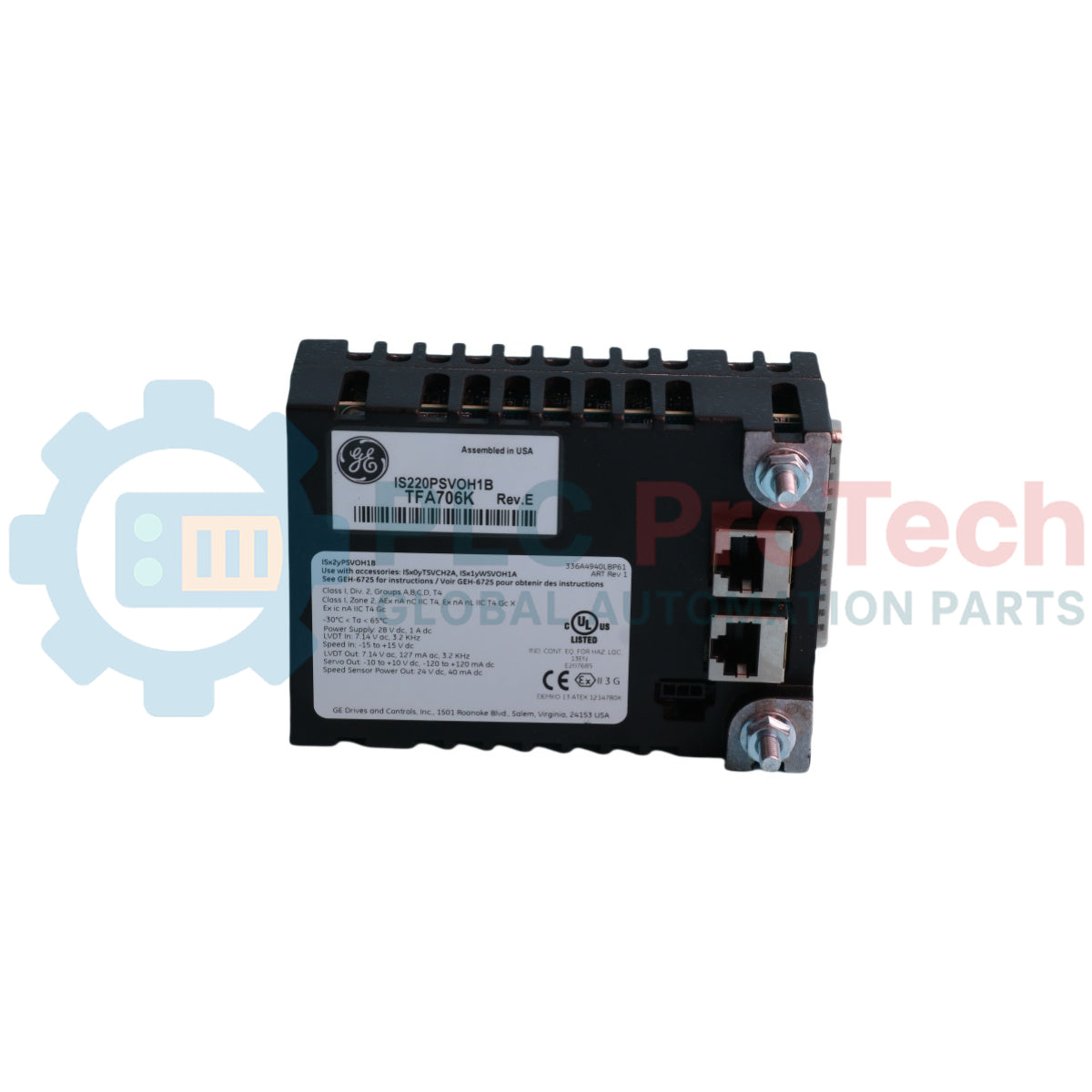
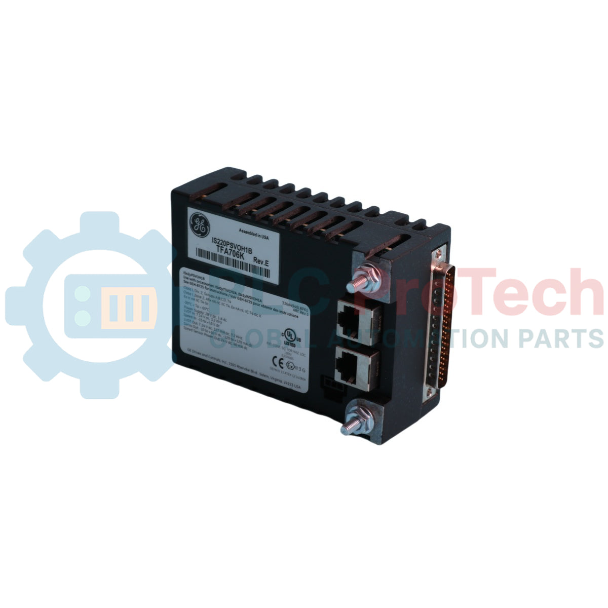
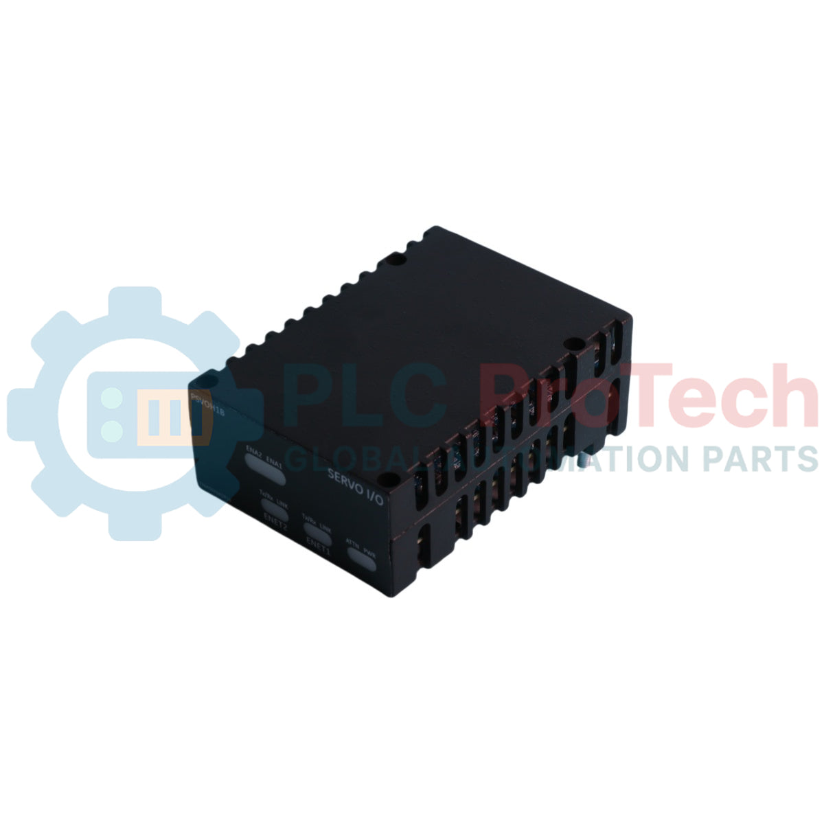
The IS220PSFDH1A is a specialized Flame Detector Power Supply pack manufactured by General Electric as part of the Mark VI Speedtronic Turbine Control System Series. This modular assembly is engineered to provide reliable, high-voltage electrical excitation directly to the flame detector circuits located on the primary gas turbine trip protection board (TRPG). Acting as a critical link within the turbine safety and flame monitoring infrastructure, the IS220PSFDH1A interfaces seamlessly through physical hardware connections to drive active optical sensors and ensure deterministic feedback verification. The base printed circuit board is protected comprehensively with a chemically-applied conformal coating layer, ensuring resilience against airborne contaminants and harsh ambient environments typical of industrial power generation facilities.
Features
- Integrated Group 1 Mark VI series modular architecture designed for high-reliability turbine trip safety integration.
- Fully passive convection-cooled hardware layout completely eliminating failure-prone mechanical cooling fans.
- Exhaustive, thin layer of chemically-applied conformal PCB coating to mitigate risks of oxidation and atmospheric tracing.
- Equipped with three dedicated faceplate diagnostic LEDs (one red, two green) indicating precise module operational states and active internal functional faults.
- Features a factory-configured, pure solid-state design requiring no manual jumper switches or hardware setting adjustments.
Applications
- Gas turbine optical flame detection monitoring loops within Speedtronic power systems.
- Centralized turbine protection arrays coupled directly to TRPG safety trip boards.
- Alternative energy infrastructures and legacy wind-power automation platforms built upon Mark VI network backbones.
Technical Specifications
| Parameter |
Specification Value |
| Manufacturer |
General Electric |
| Part/Model Number |
IS220PSFDH1A |
| Functional Abbreviation |
PSFD |
| Product Series |
Mark VI Speedtronic |
| Assembly Classification |
IS220 Special Assembly (Group 1 Layout) |
| Primary Functional Revision |
A (Alters baseline performance and electrical execution) |
| Maximum Input Voltage |
29.4 V dc |
| Startup Operational Time |
34 mS (At full load with 28 V dc input source) |
| Full-Load Power Consumption |
4.1 W |
| Maximum Open-Circuit Output Voltage |
355 V dc (At zero load with 29.4 V dc input) |
| Local Output Diagnostic Interface |
Differential pair TP test points |
| Physical Enclosure Geometry |
Rectangular industrial housing |
| Working Temperature Range |
-30 degrees Celsius to +65 degrees Celsius |
| Cooling Methodology |
Natural Convection (Fanless) |
| Country of Origin |
United States (Domestic GE Manufacture) |
Connections and Interfaces
| Interface Connection |
Function / Circuit Assignment |
| J3 Connector |
Flame detector power supply circuit link 1 to TRPG board |
| J4 Connector |
Flame detector power supply circuit link 2 to TRPG board |
| J5 Connector |
Flame detector power supply circuit link 3 to TRPG board |
| TP Test Points |
Differential hardware probe points for local output voltage verification |
| Faceplate IR Port |
Infrared port (Not used / Inactive in production assembly) |
Application Pitfalls & Engineering Notes
Engineers should note that the internal step-up circuitry of this module generates high-voltage operational spikes reaching up to 355 V dc under zero-load conditions given a maximal input profile of 29.4 V dc. Ensure appropriate voltmeter instrumentation is set to withstand high-voltage ranges when troubleshooting local test points. The integrated infrared (IR) interface located on the front panel faceplate remains non-functional and must not be used for diagnostic calibration sequences.
Commissioning & Wiring Tips
When monitoring live operational parameters during start-up tracking loops, connect calibrated multi-meter leads carefully across the differential pair of TP test points. Given that this module outputs high potential within 34 milliseconds from full-load engagement, transient verification should be performed using storage-type digital oscilloscopes to correctly isolate output ripple factors or installation tracking noise.
Installation Guidelines
CRITICAL WARNING:
This device generates open-circuit potential up to 355 V dc. Disconnect and verify absolute zero energy on all primary DC input networks before handling interface modules or tracking structural wires. Touching active connections will result in severe electrical shock injuries or immediate card short-circuit failure.
1
Mount the rectangular pack assembly directly above the TRPG (primary gas turbine trip protection board) on a stable sheet metal surface structure.
2
Secure the assembly base mechanical layout using specified mounting studs, mounting brackets, and the designated mounting plate to limit physical shock deformation.
3
Firmly couple the primary power routing interfaces into connectors J3, J4, and J5 on the TRPG board to establish complete signal path paths for the flame detection array.