Honeywell

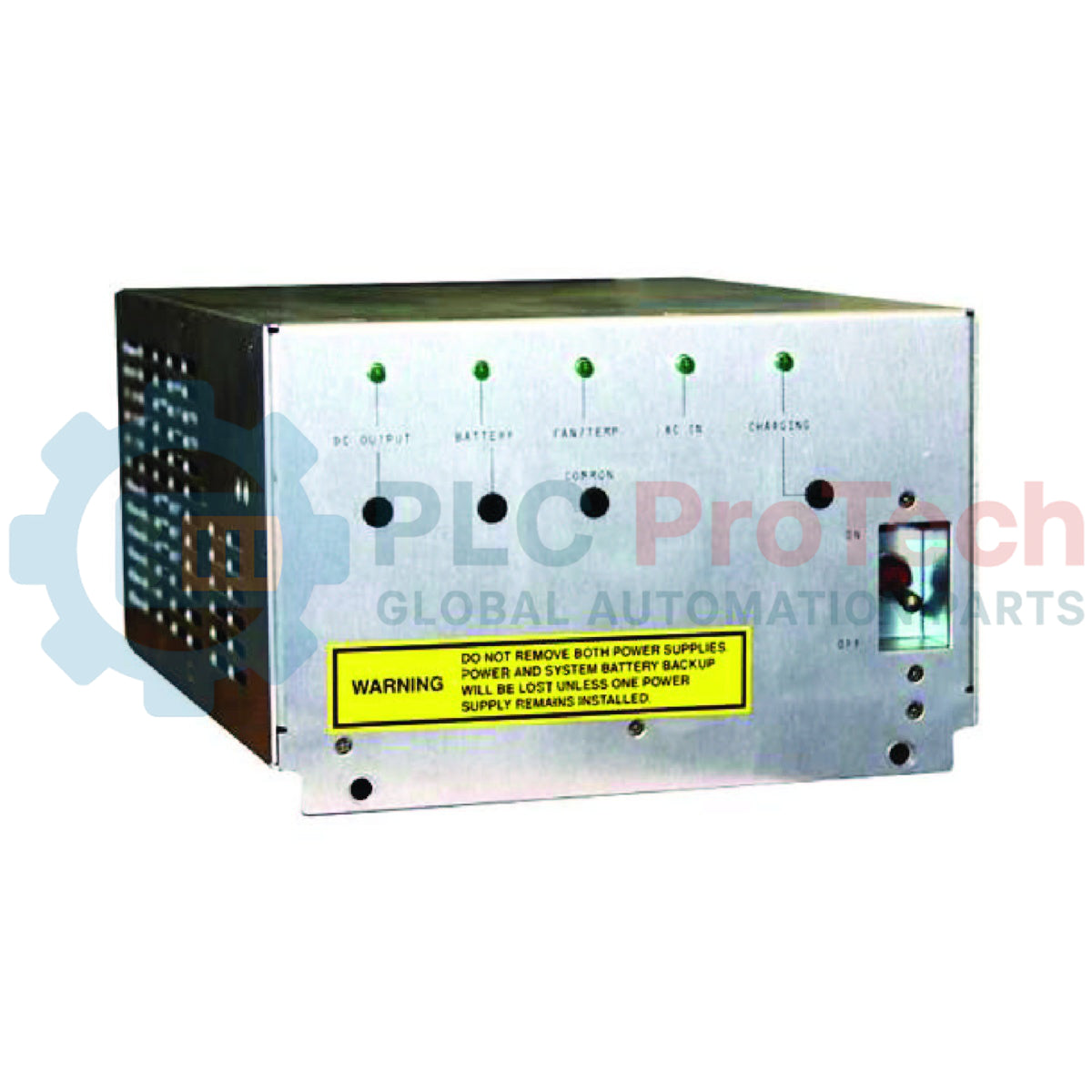
Honeywell 51198947-100 Process Manager HPM Power Supply Module

SKU 51198947-100

In stock
  • 12-month warranty
  • Free returns within 30 days
  • Manufacturer: Honeywell

  • Product No.: 51198947-100

  • Country of origin:United States

  • Product Type: Power Supply Module

  • Payment: T/T, Western Union

  • Weight: 5000g

  • Dimensions: 280 x 150 x 220 mm

  • Shipping port: Xiamen

  • Warranty: 12 months

Description

The Honeywell 51198947-100 is an AC input, AC/DC output power supply module engineered specifically for Honeywell Universal Control Network (UCN) equipment cabinets, including Process Manager (PM), Advanced Process Manager (APM), and High Performance Process Manager (HPM) systems. Operating from a wide line voltage range of 85 to 264 VAC or a 48 Vdc auxiliary battery system, it serves as a central power distribution and backup unit within Honeywell DCS architectures.

This module features a regulated DC output nominally rated at 25.25 Vdc at a 10 A load during AC line operation, and transitions to 24.25 Vdc when operating on 48 V battery power. Integrated into its design is an active battery charging circuit for 48 V auxiliary battery banks, alongside a nominal 6 Vac line-frequency output rated at 35 mA dedicated to system line-frequency synchronization.

The 51198947-100 is equipped with extensive diagnostic monitoring and dedicated LED indicators for DC Out, Battery, Fan/Temp, AC In, and Charging status. Internal dry annunciator contact outputs seamlessly integrate into system alarm schemes to alert operators to power failures, overtemperature conditions, fan degradation, or battery circuit faults. Designed for high-reliability environments, two or more modules can be configured with outputs wired in parallel to establish redundant power configurations.

Features

  • Wide Input Range: Accepts 85 to 264 VAC line input or secondary 48 Vdc battery backup power.
  • Dual-Mode Regulated DC Output: Delivers 25.25 Vdc at 10 A under standard AC power and 24.25 Vdc under 48 V battery operation.
  • Integrated Battery Charger: Built-in charging circuit engineered to maintain auxiliary 48 Vdc battery banks in float standby service.
  • Line Frequency Synchronization: Provides a nominal 6 Vac, 35 mA line-frequency reference output for system timing synchronization.
  • Comprehensive Visual Diagnostics: Front-panel LED indicators monitor DC Out, Battery Status, Fan/Temperature, AC Input, and Battery Charging states.
  • Hardware Alarm Contacts: Integrated relay annunciator contacts open automatically upon loss of AC input, DC output fault, internal overtemperature, fan failure, or battery charger fault.
  • Redundant Configuration Support: Engineered for parallel output operation across two or more units to ensure uninterrupted system uptime.
  • CE Compliant Architecture: Meets applicable European Economic Community (EEC) directives for industrial safety and EMC performance.

Applications

  • Honeywell DCS Cabinets: Provides main operating power and backup battery control for PM, APM, and HPM UCN cabinet assemblies.
  • System Clock Synchronization: Delivers line-frequency AC synchronization signals to process control modules.
  • Redundant Industrial Power Schemes: Serves as a hot-swappable or parallel power module in mission-critical process automation enclosures.

Technical Specifications

Parameter Specification
Manufacturer Honeywell
Product No. 51198947-100
Product Type HPM Power Supply Module
Cabinet / System Compatibility Honeywell UCN Equipment (PM, APM, HPM)
Input Voltage (AC Line) 85 to 264 VAC
Input Voltage (DC Battery) 48 Vdc
Nominal DC Output (AC Line Powered) 25.25 Vdc @ 10 A load
Nominal DC Output (Battery Powered) 24.25 Vdc
Synchronization Output Nominal 6 Vac, line-frequency @ 35 mA load
Battery Charger Circuit Integrated 48 Vdc charging circuit
Operating Temperature (Full Load) -20 to +55 degC
Derating Capability Derates linearly above 55 degC at 0.5 A/degC up to +65 degC max
Paralleling Capability Supported (Two or more units with outputs paralleled)
Directives / Compliance CE Compliant, EEC Directives
Diagnostic LEDs DC Out, Battery, Fan/Temp, AC In, Charging
Alarm Contact Outputs Annunciator contacts for DC Out, AC In, Fan/Temp, Battery, and Charging
Shipping Weight 5 kg

Connections / Interfaces

Interface / Signal Function
AC Input Terminals Line voltage power input (85-264 VAC)
48 Vdc Battery Terminals Interface for external 48 V backup battery bank and charging circuit
DC Output Pins Nominal 25.25 Vdc / 24.25 Vdc power distribution output
Sync Output Nominal 6 Vac line-frequency output for system synchronization
Alarm Contact Terminals Dry contact outputs for remote monitoring of power, temp, fan, and charging faults

Installation Guidelines

  1. Safety Pre-Check: Verify that input line voltages match the rated 85–264 VAC operating range before applying mains power.
  2. Cabinet Airflow: Ensure the cabinet installation allows unhindered airflow around the module's cooling fan and heat dissipation paths.
  3. Grounding: Verify that protective earthing (PE) and cabinet ground bonding conform to Honeywell installation guidelines prior to powering the unit.
  4. Wiring Verification: Ensure positive, negative, and earth connections to the 48 V battery bank and DC bus bars are wired with correct polarity and secure terminations.
  5. Parallel Setup: When installing units in a parallel/redundant setup, confirm that load connections are balanced according to system documentation.

Replacement Recommendations

  • Off-Process Replacement: Where possible, perform module replacement off-process during scheduled maintenance windows to mitigate environmental risks and avoid pulling airborne contaminants into adjacent running power supplies.
  • Redundant Swap Protocol: If performing a live swap in a redundant dual-supply system, exercise caution to avoid introducing airborne particulates that could impair the active supply's cooling fan.
  • Diagnostic Check: Following replacement, verify that all five front-panel LEDs (DC Out, Battery, Fan/Temp, AC In, Charging) illuminate solid green, confirming normal system operation.

FAQ

What is the primary function of the Honeywell 51198947-100 power supply module?

The Honeywell 51198947-100 provides main regulated DC output power (25.25 Vdc at 10 A) to Honeywell UCN equipment cabinets, including PM, APM, and HPM systems. It accepts wide AC line inputs or 48 Vdc battery inputs, manages backup battery charging, and provides line-frequency synchronization signals.

What happens to the DC output voltage when the supply switches to 48V battery backup?

When powered from the AC line, the nominal DC output voltage is 25.25 Vdc at a 10 A load. When operating on secondary 48 Vdc battery backup power, the nominal output voltage transitions to 24.25 Vdc.

Can multiple 51198947-100 power supply modules be used together for redundancy?

Yes, two or more 51198947-100 power supply modules can have their DC outputs connected in parallel. This enables redundant power configurations within Honeywell process manager cabinets to protect against unexpected power outages.

What do the front-panel LED indicators on the 51198947-100 monitor?

The module features five diagnostic LED indicators: DC Out, Battery, Fan/Temp, AC In, and Charging. When all five LEDs are fully illuminated, the power system is operating within normal parameters without active fault conditions.

How does the power supply handle high ambient operating temperatures?

The module operates at full load capacity from -20 to +55 degC. Above 55 degC, output capability derates linearly at 0.5 A/degC up to a maximum operating limit of +65 degC.

View all FAQs →

Product Documentation

Technical Datasheet (PDF) Complete specifications and technical drawings.

Technical Datasheet

Honeywell 51198947-100 Process Manager HPM Power Supply Module

Quantity
Shipping & Returns

Global Express Shipping

  • Standard Delivery: 4–6 business days via DHL, FedEx, and UPS.
  • Express Dispatch: Same-day dispatch for in-stock orders placed before 2:00 PM (GMT+8).
  • Worldwide Coverage: Serving over 150 countries.

Returns & Warranty

  • 30-Day Guarantee: Returns accepted for in-stock products in original, factory-sealed packaging.
  • 12-Month Warranty: Every industrial component is backed by our technical warranty.
Reviews
1 of 1
Only 7 item(s) left in stock
Quantity
View full details

Global Express Shipping

  • Standard Delivery: 4-6 Business Days via DHL, FedEx, and UPS.
  • Express Dispatch: Same-day dispatch for in-stock orders placed before 2:00 PM (GMT+8).
  • Worldwide Coverage: Serving over 150 countries, including rapid delivery to Saudi Arabia and UAE.

Returns & Warranty

  • 30-Day Guarantee: Returns accepted for in-stock products in original, factory-sealed packaging.
  • 12-Month Warranty: Every industrial component is backed by our professional technical warranty.

Orders are processed and delivered Monday-Friday (excluding public holidays).


For full eligibility, restocking fees, and international return details, please view our official Refund & Return Policy .

TECHNICAL SPECIFICATIONS

Color pattern
Silver
Country of origin
United States

Technical knowledge

Allen-Bradley 1771-IG: TTL Logic and 5 V Wiring Checks

Check 1771-IG TTL HIGH/LOW logic thresholds, field supply ripple and 1771-WC wiring before replacing an input module.

AKS 33 vs AKS 3000: Checks Before Replacing a Pressure Transmitter

A field checklist for distinguishing Danfoss 060G2105, 060G1323 and 060G2109 by pressure range, fitting, loop signal and controller scaling.

Diagnosing DeltaV SE5009 Power Problems Before Replacement

A field checklist for separating 24 VDC input, carrier bus, output derating and alarm-contact faults before replacing an Emerson SE5009.

Commissioning Quantum Inputs with the 140XSM00200 Simulator

A controlled commissioning method for using the 140XSM00200 simulator to verify Modicon Quantum input mapping and interlocks before reconnecting field wiring.

Commissioning PLX32-EIP-MBTCP: Subnets, Registers, and RPI

A commissioning checklist for the ProSoft PLX32-EIP-MBTCP covering subnet separation, register contracts, EtherNet/IP timing, failure tests and replacement records.

Diagnosing IC693MDL916 Relay Outputs Before Module Replacement

A field checklist for IC693MDL916 relay commands, terminal blocks, load current, switching rate and contact-side measurements.