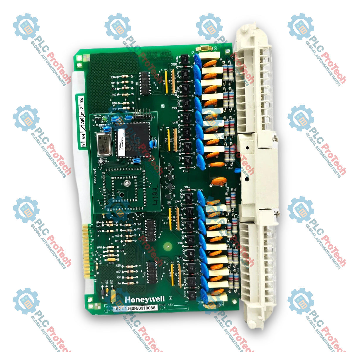
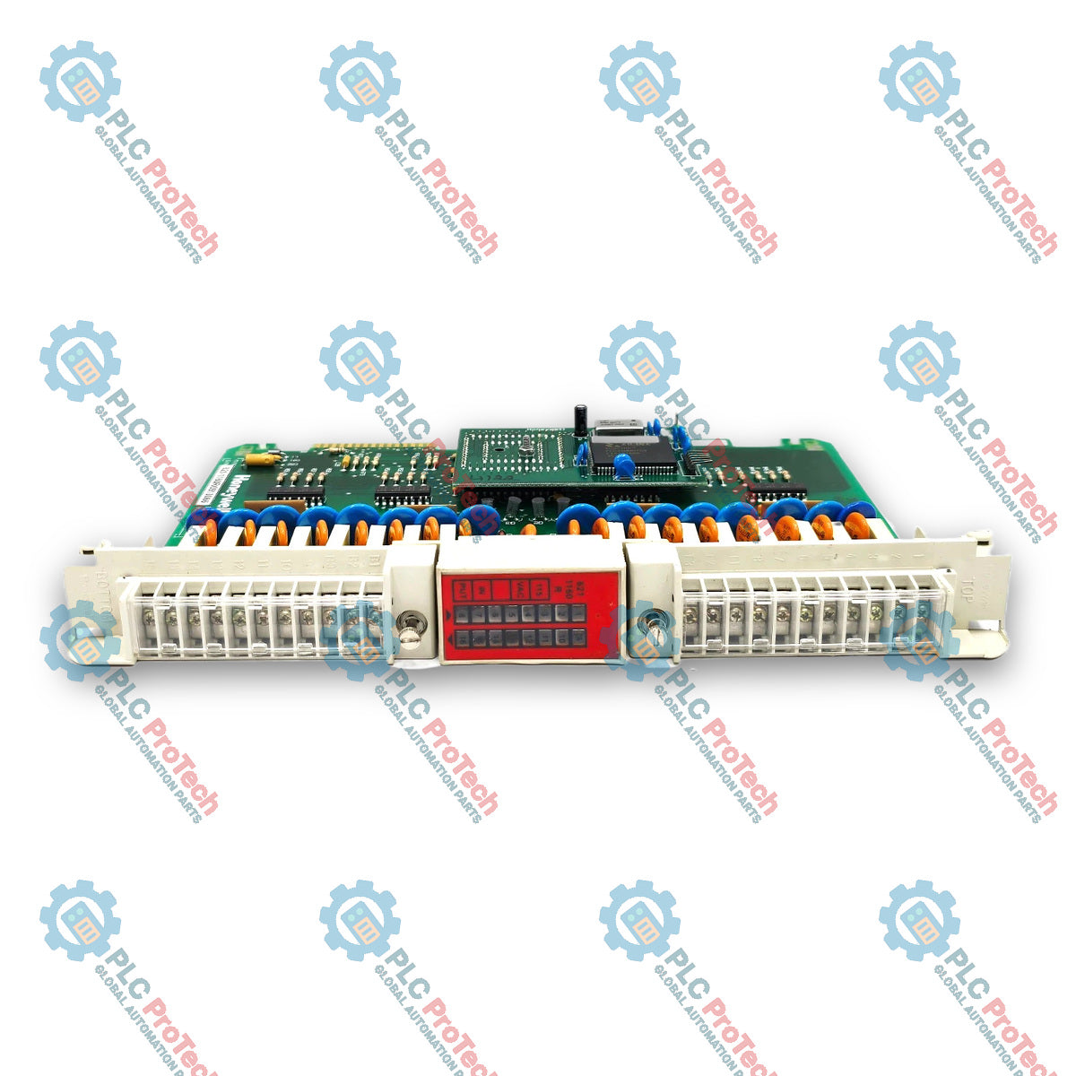
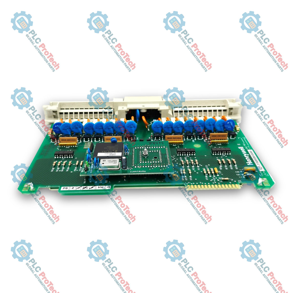
Honeywell 621-1160R Logic Manager Digital Input Module
SKU 621-1160R
In stock
No reviews
12-month warranty
Free returns within 30 days
Manufacturer:
Honeywell
Product No.:
621-1160R
Country of origin:United States
Product Type:
Digital Input Module
Payment:
T/T, Western Union
Weight:
1300g
Dimensions:
50 mm x 290 mm x 220 mm (W x H x D)
Shipping port:
Xiamen
Warranty:
12 months
Description
The Honeywell 621-1160R is a digital input module designed for monitoring AC discrete field signals in Logic Manager systems on the Universal Control Network (UCN). Operating across an 80-140 Vac voltage range with a 115 Vac nominal rating, the 621-1160R processes status signals from field switches, pushbuttons, and industrial sensors into the Logic Manager Control Processor memory. The module provides 16 input channels configured on a single common connection, utilizing standard internal backplane power (+5 Vdc) with built-in input surge current limiting.
Features
Provides 16 discrete input channels routed through a single common point
Configured for IEEE 518 DATA 3 signal level wiring classification
Integrates hardware current limiting rated up to 500 mA per input point
Features built-in signal filtering delays for noise rejection
Applications
Pushbutton and selector switch monitoring
Limit switch and proximity contact sensing
Motor starter auxiliary contact monitoring
Discrete AC interlock system feedback
Technical Specifications
Parameter
Specification
Manufacturer
Honeywell
Point Inputs
16
Points Per Common
16
Nominal Voltage
115 Vac
Voltage Range
80-140 Vac
Current Range
4-15 mA (8 mA at 115 Vac typical)
Switching Level - Logic 1
75 Vac
Switching Level - Logic 0
43 Vac
Allowable Leakage Current
1.5 mA ac
Input Delay - Off to On
2.4 ms +-25%
Input Delay - On to Off
30 ms +-50%
Operation Current (+5 Vdc)
50 mA max
Input Surge Current Limit
500 mA per input
IEEE 518 Wiring Class
DATA 3
Shipping Weight
1.3 kg
Installation Guidelines
Verify that incoming discrete AC input voltages remain strictly within the 80-140 Vac operating range.
Ensure total off-state leakage current from connected field devices does not exceed 1.5 mA ac per channel.
Route input field wiring according to IEEE 518 DATA 3 signal class guidelines to prevent noise coupling.
Ensure proper insertion into the designated I/O card file slot before applying field power.
FAQ
What threshold voltages define the logic states for the module inputs?
The module recognizes Logic 1 at 75 Vac minimum and Logic 0 at 43 Vac maximum.
What is the maximum allowable off-state leakage current for connected sensors?
Connected field devices must maintain off-state leakage current below 1.5 mA ac to prevent false input triggering.
What signal class standards govern field wiring for this device?
Field connections follow IEEE 518 DATA 3 wiring class specifications for proper noise isolation.
A practical replacement guide for the GE Fanuc IC693CPU313, covering its embedded five-slot architecture, memory backup, firmware-dependent capacity and why it cannot use Series 90-30 expansion racks.
A field-focused comparison of Bently Nevada 3500/40M and 3500/42M monitor inputs, channel-pair configuration, rear I/O options, external termination hardware and firmware checks before replacement.
A field checklist for diagnosing Allen-Bradley 1746-NR4 RTD and resistance inputs, including sensor curves, lead compensation, excitation current, filter timing and channel diagnostics.
A field-focused checklist for replacing an Allen-Bradley 1785-L40B or planning a PLC-5/40 migration, covering backups, 1771 I/O mapping, DH+/RIO channels, revision risks and commissioning.
Replacing an Allen-Bradley 1747-SN scanner? Check SLC 500 logical rack and G-file mapping, link speed, cable termination, COMM/FAULT LEDs and hardware series before blaming the module or changing the...